User guide
Walls
Draw walls corner by corner, change them in the properties panel, and set up wall types with their layers.
Drawing walls
Open the Architecture tab and choose Wall, or type WA.
While the tool is on, the properties panel shows New element: the type the walls are drawn with. Choose another there before the first click, and see its layers, its thickness and how many walls already use it; Edit types… opens Wall types. Door, Window, Floor, Ceiling and Curtain wall show their types the same way.

Click where the wall starts, then click at each corner. The next wall follows the mouse. While you draw, you can type a length and an angle in the boxes above the view instead of clicking. Press Enter to end the chain (the walls drawn stay; the next click starts a new one), or Esc to drop the wall in progress; a second Esc leaves the tool (see Enter and Esc).
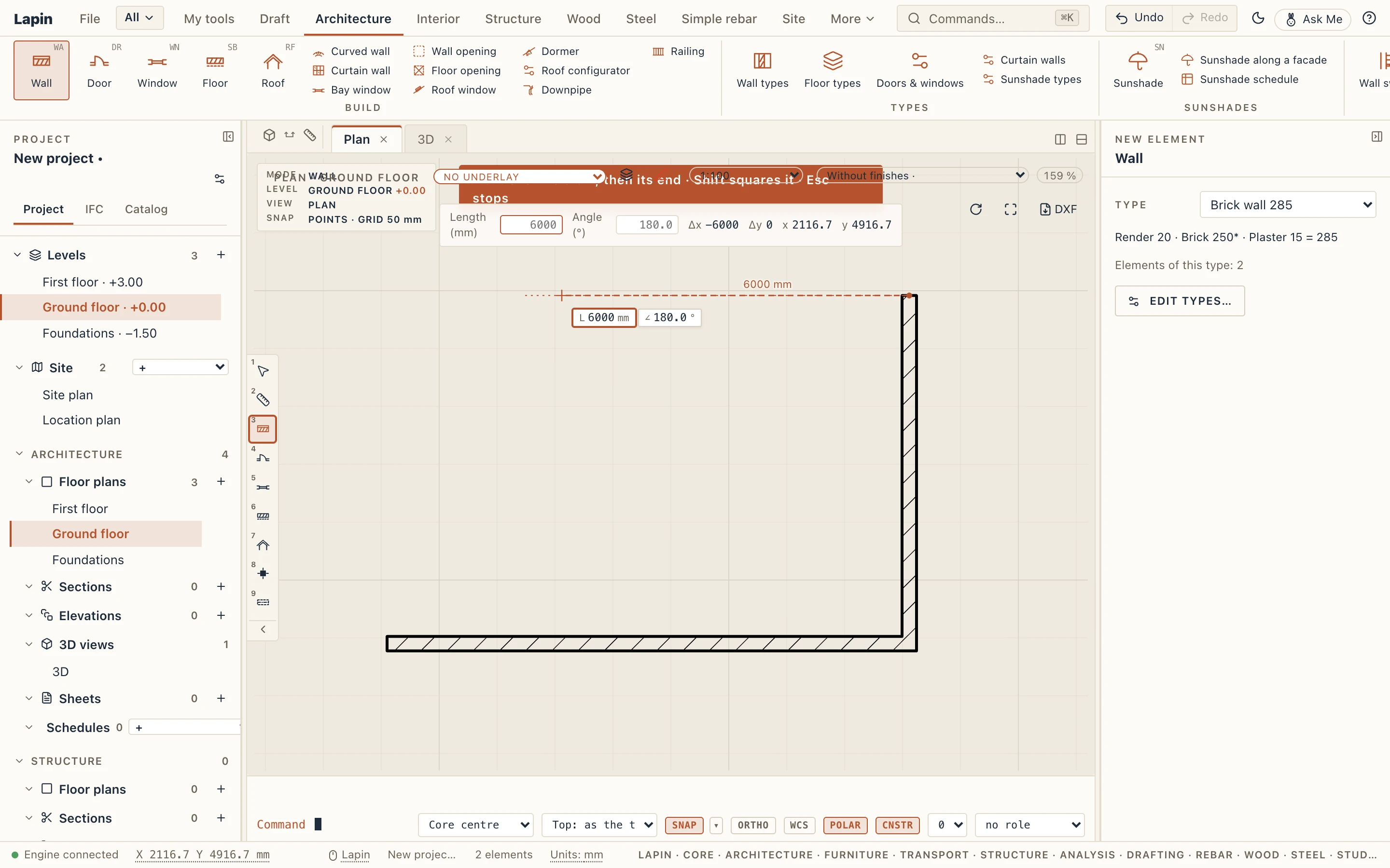
Where two walls meet, Lapin joins them by itself. Their layers run into each other the way they would be built.
- Wall draws straight pieces, each starting where the last one ended. The command line's bar has a Line / Arc choice: with Arc, click the start, the end, then a point the arc passes through. Curved wall (WC) starts the Wall tool already set to Arc.
- Curtain wall (CW) draws a glazed wall with mullions and panels; its type can take their real shape from a profile library.
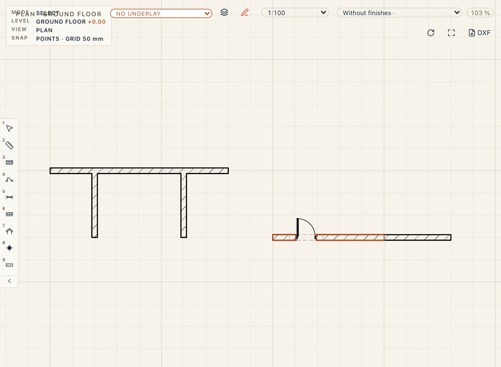
- Walls join by themselves where they meet: a corner as a mitre, a wall ending on another as a T, one crossing another as an X. At a T or an X the layers run into each other as built: the ending wall's core goes on through the other's finishes to its core, and its finishes stop at the other's face, meeting their like, so the plan shows one build-up with no line through it. Join walls (JW), Mitre and Butt change how two walls meet when that is not what you want; Mitre new corners makes butt the default on this computer. Either way, each layer turns the corner on its own: the finishes meet their like and run round unbroken, and the cores meet on the diagonal (mitre) or one core runs on to the other's outer face (butt), so a plan of layered walls shows clean corners. Each layer goes on into the other wall through its layers of a lower Priority and stops at the first as high or higher (see Wall types below), so by default cores meet cores and finishes stop at the faces; at a corner, a core of a higher priority runs through the other's, mitre or butt. A wall's Cut priority never takes it into a wall it is joined to: between joined walls it only decides which core runs through when both cores have the same priority (at a butt corner or a crossing). A wall you move, turn, mirror, copy or array joins what it lands on the same way, in the same undo step, and a join it leaves behind goes; walls moved or copied together keep their joins among them as they were, and so do an array's items (they join what they land on, not each other). A wall recognised from an imported IFC keeps the file's joins when you move it; a copy of it is your own wall and joins.
- Mitre, Butt and Swap (the Joins group, shared with beams and footings) change how the corners of the selected walls meet; Swap changes which of the two walls runs through.
- Join automatically at start and Join automatically at end, in a wall's properties (a beam's and a strip footing's too), say whether each end joins what it meets by itself; they apply to every wall selected. An end turned off keeps the joins it has (Join walls still makes one there, and the join tools take it off), makes no new one, and no other wall's end is brought to it, so the wall keeps its length and its ends whatever is drawn or edited round it. Right-click a selected wall's end grip for Don't join at this end (or Join automatically at this end, which joins what it meets there at once). The ends of walls imported from an IFC file start off: they stay as the file has them when you change their height, type or length, and their doors and windows stay where they are in plan when their start moves.
The line you draw on. While the Wall tool is on, the list in the command line's bar chooses the line you click: Core centre (the axis, as before), Core, exterior face, Core, interior face, Exterior face or Interior face. The exterior is the wall's right as you draw (draw round a building anticlockwise to have it outside). The wall's axis stays on its core, set off from the line, and walls drawn one after the other on the same face meet at the corner of that face.
A layered wall from solids
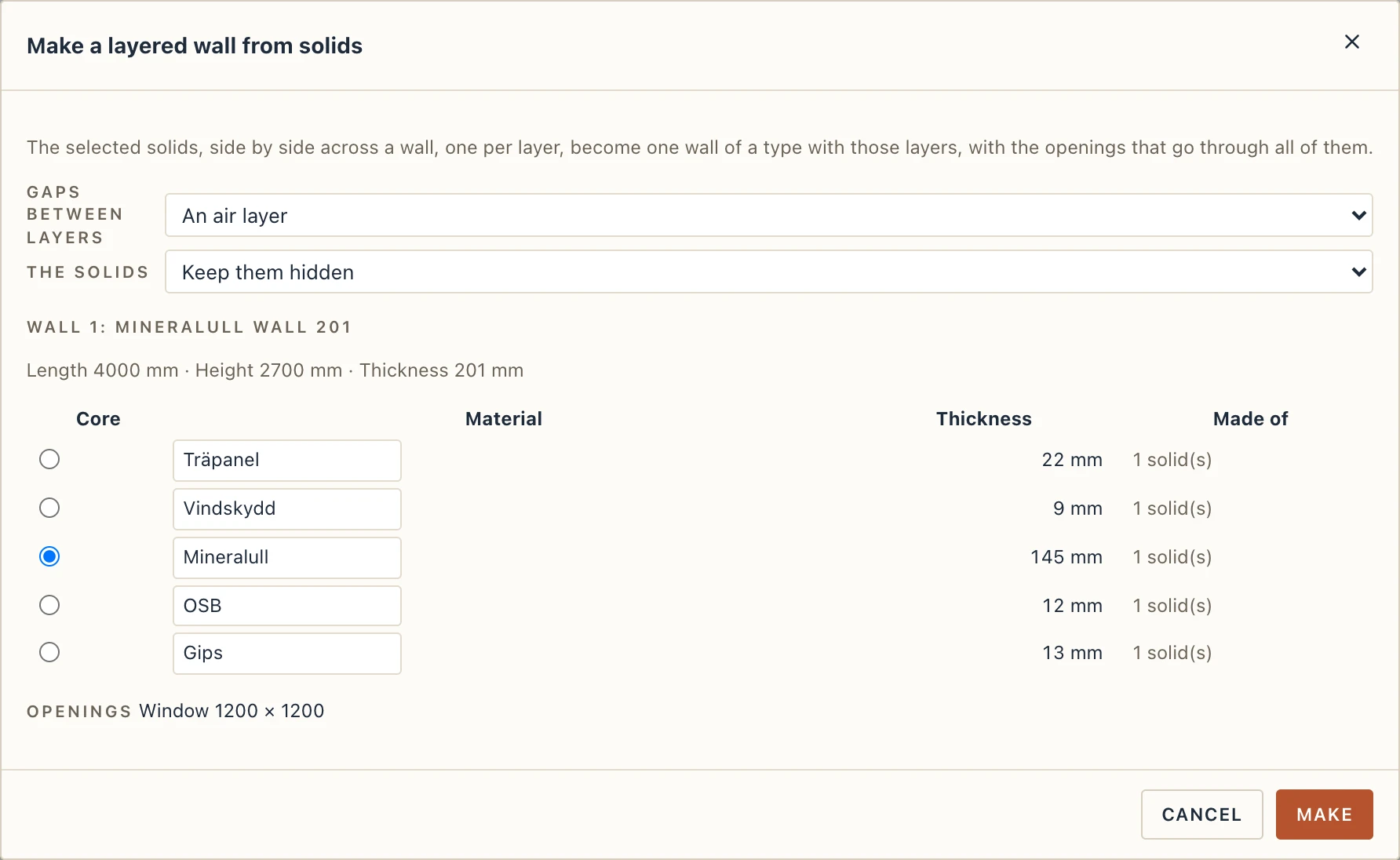
A wall another program modelled as separate solids, one per layer (a timber-frame wall drawn in SketchUp as its cladding, battens, boards, insulation with its studs and gypsum), becomes one Lapin wall with Architecture → Wall from solids (WFS), or Make a layered wall… when you right-click the selected solids. Select them first: references an IFC, SKP, OBJ, glTF or DAE import brought, Studio solids, or a group holding them. Lapin reads them from their triangles: the solids running the same way, overlapping along and up, side by side across with no more than 10 cm between them, are one wall, and each set of them another wall. Across each wall, the solids that share a stretch of its thickness are one layer, in the order they lie.
Before anything is made, the dialog shows each wall it found: its length, height and thickness, its layers with their materials and thicknesses (rounded to a millimetre), its openings, and what differs from the solids by more than 1 mm or 0.5 % of a layer's volume, as an import measures it; click a name to select that solid. You choose:
- Gaps between layers: An air layer of the gap's thickness, or Into the thicker neighbour.
- Each layer's Material: the solid's material, else its name (Gips 2 reads Gips); a layer marked in orange names none, so type one.
- The Core, where the wall's axis runs and which joins: the structural layer by its name (concrete, brick, timber frame…), the layer with studs, else the thickest.
- Timber frame layer (with the wood module): the studs found in a layer (7 × Regel inside) make it the core and a timber frame of their section and spacing (45x145 mm at 600); without it, the layer is of the insulation's material and the studs are only reported.
- The solids: Keep them hidden (no view draws them and no export writes them while the wall is there; the wall's properties offer Show the original solids, and deleting the wall brings them back), Delete them, or Keep them.
Make makes a wall type with those layers (no lintels: what the solids have, nothing more) and the wall on its axis, as long and as high as the core's solids, on their storey and in their group. An opening found in every layer that runs past it becomes the wall's opening, as large as the smallest of them; a door's or window's solid standing in it (an IfcDoor or IfcWindow, or one named so) becomes a door or a window of that size. An opening in some layers only is listed and the wall is left whole there. Walls made together are joined where they meet. All of it is one step to undo. Nothing is done on its own when a file is imported: the file comes in as it is, and the wall is made only when you ask.
Changing a wall
Click a wall to select it. Its grips appear. Drag the ends to lengthen or shorten it, or drag the cross in the middle to move it.
In the 3D view a selected wall has three more grips: one on its top, to drag its height (or its top's offset, when its top goes to a storey), and one on each face, to move it sideways (a curved wall's radius). See Grips and components in 3D.
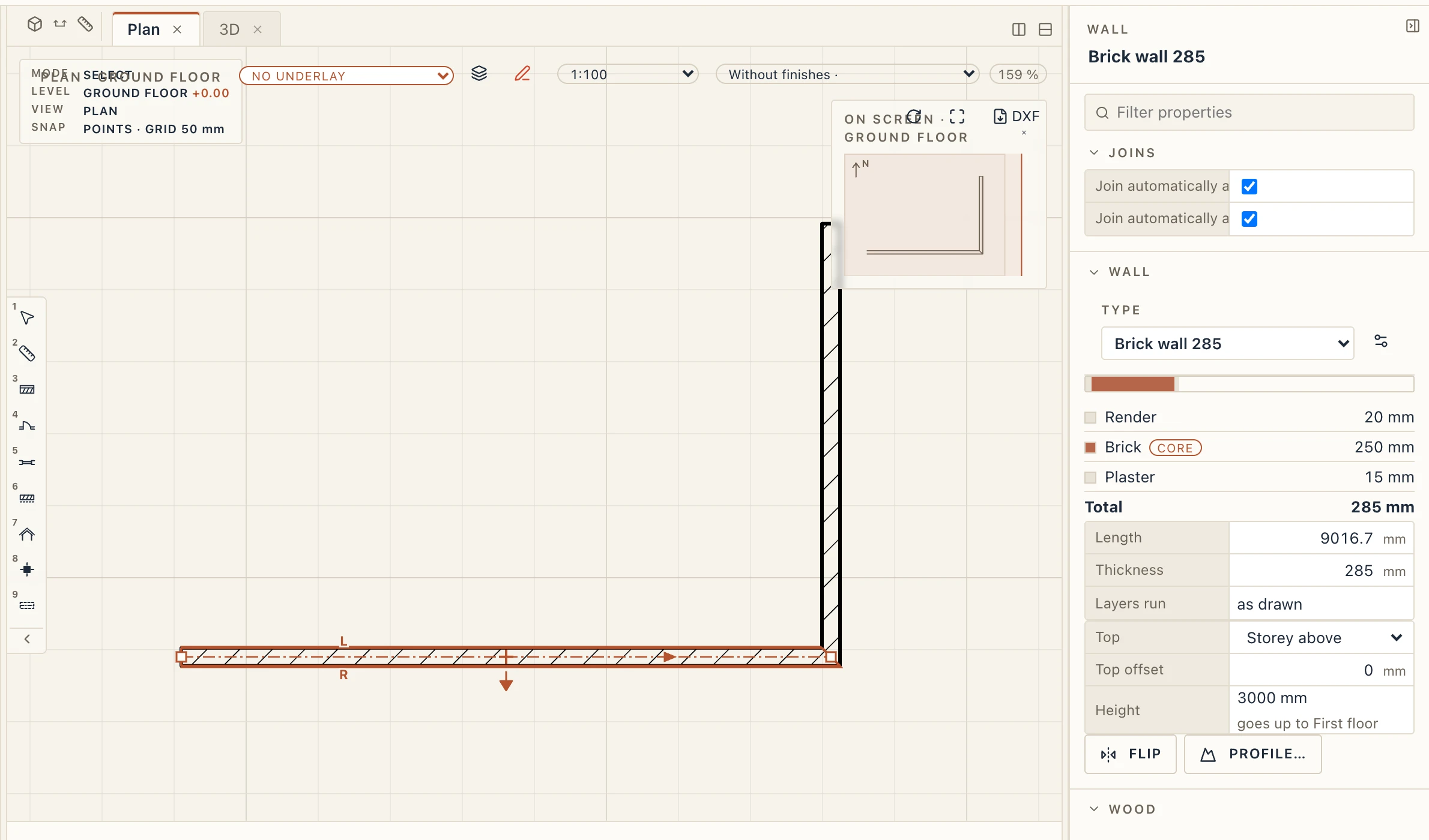
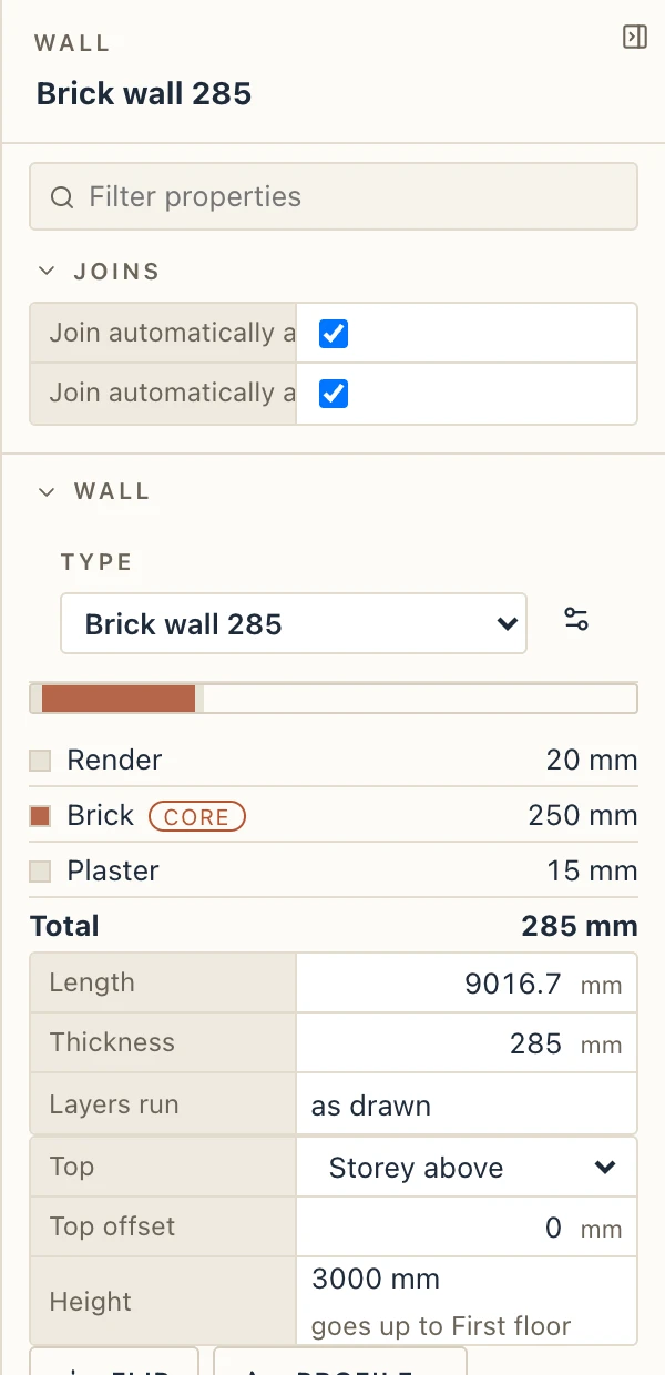
The properties panel shows the selected wall. The top of the panel holds its type and layers. Below that are its length, height, base offset, storey and phase. Change any value and the model follows. Each wall's values are its own. Its Thickness comes from its type's layers: type a new one and the selected walls take the type with the same build-up and that thickness, the core resized and the finishes kept. Lapin uses the project's type if one has exactly that build-up, else it makes one named after theirs (Partition wall 130mm becomes Partition wall 150mm). The other walls of the old type stay as they are, and Ctrl Z undoes it in one step.
Rounding or cutting a corner
Architecture → Fillet (the command line's FILLET, F) rounds the corner between two walls with a curved wall: type the radius (Enter keeps the last one), then click the first wall and the second. Both are trimmed back to where the arc touches them, or carried on to it when they do not reach the corner yet, as CAD's fillet does with two lines. The curved wall is the first wall again (its type, height, base, top and layers, on the same side) and is joined to both. Click each wall on the part to keep: where two walls cross, the other parts go. A radius of 0 makes a sharp corner, both walls carried on to meet. Architecture → Chamfer (CHAMFER) cuts the corner with a straight wall instead, its distance measured along each wall from the corner. Right-click a selected wall's end grip where it meets another wall for Fillet corner… and Chamfer corner…, the radius or distance typed. Each is one step of undo.
The radius is the walls' axis's, the middle of their core. Type I (Inside) or O (Outside) before picking to give the radius of the inside or the outside face of the bend; A goes back to the axis. The two walls keep their ids (their GlobalIds in IFC), and their doors, windows and openings stay where they are in plan; one that would fall in the part cut away refuses the fillet (a smaller radius, or move it first). Walls of different types, heights or bases are filleted only when you answer Yes to take the first wall's. Curved walls, and walls with a profile of their own, are not filleted.
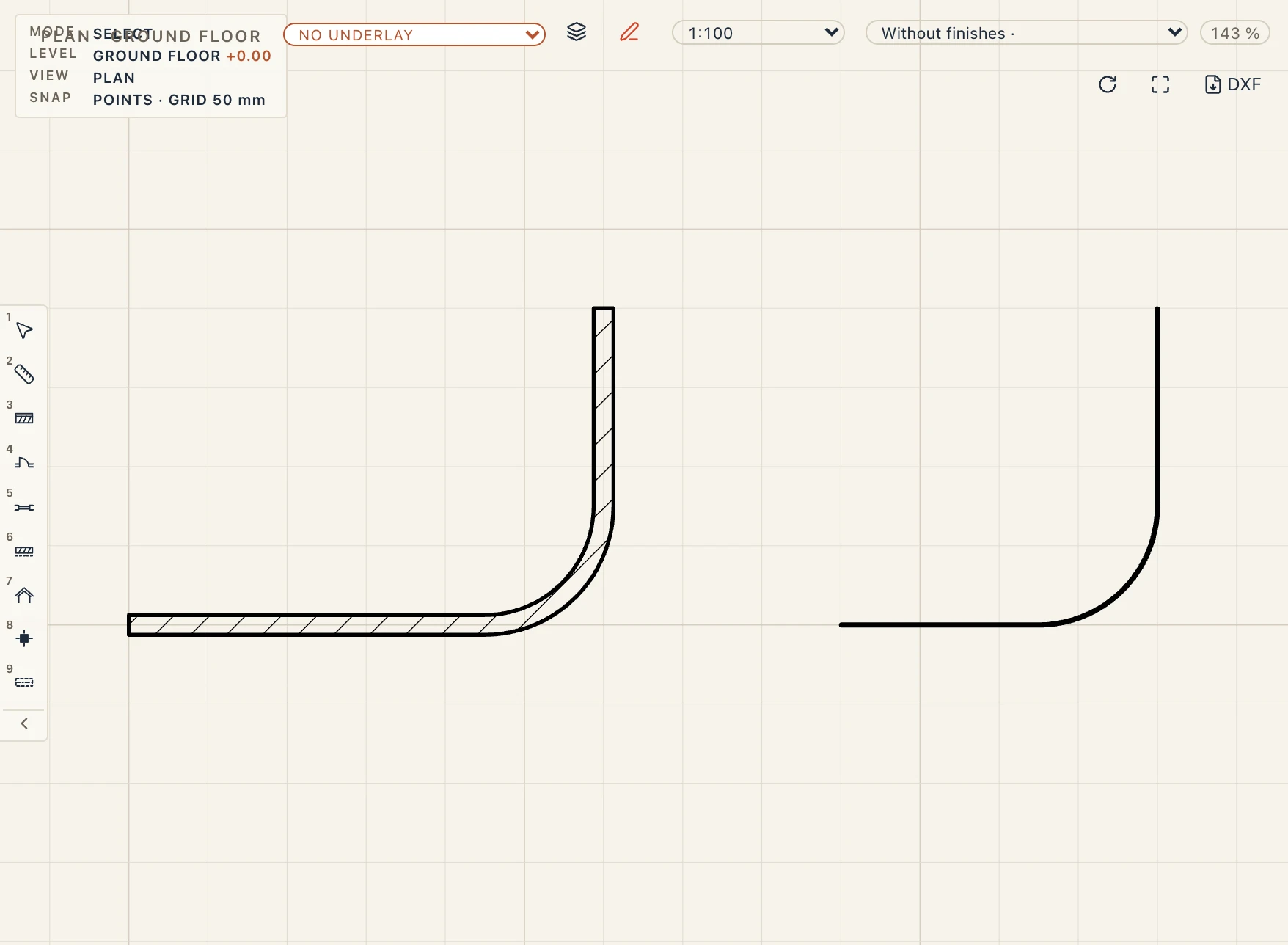
The wall's top
A wall goes up to the level above by itself. Its Top, in its properties, says where it goes:
- Storey above (a new wall's default): to the level of the storey above its own. On the topmost storey, to that storey's own top (its level and height).
- a storey of the project: to that storey's level, two storeys up for a wall through a double-height hall.
- Unconnected height: to a height of its own, the Height you type.
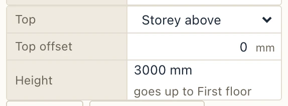
Top offset is added to the level it goes to: −300 stops a wall under a floor's structure, +900 takes a parapet over the roof's level. The Height shown below is worked out from the storeys every time, so raising or lowering a storey (its Base level in its properties) moves the tops of the walls going to it, and lowering the storey a wall stands on lowers its base and keeps its top. Their joins, layers that stop at a height, doors and windows, sweeps, quantities, schedules, drawings and the IFC export all follow. A change reaches every selected wall in one step.
A top that would come at or below the wall's base is refused; one that comes so later (the storey above brought down to the wall's) leaves the wall at its own height, and Problems says so. Deleting a storey lets the walls going to it stand unconnected at the height they had. Copy to storeys sends a copy as many storeys up as the original went. Typing a height in a wall's properties makes it unconnected. Attach to roof still takes the wall up to a roof's underside from wherever its top is.
While the Wall tool is on, the list after the line's in the command line's bar chooses the top of the walls you draw: as the type, storey above or a storey with an offset, or unconnected height with a height. A wall type gives its walls a top too: Wall top in Wall types, under the lintels, is the storey above with an offset (−450 for walls under the beams) or an unconnected height (1100 for a parapet type). Walls drawn before this stay at the height they had (unconnected); walls from an IFC file stand as the file says, and Lapin's own IFC files bring their tops back.
Further down, Dependencies shows what is built from the wall and what the wall is built from. Used by lists the elements that change when the wall changes: the walls it joins, its doors and windows, a wall attached to it. Click a name to select that element. Built from lists the elements the wall depends on, then its type and materials. When you delete an element that others depend on, a message names the ones that were rebuilt; Ctrl Z brings everything back.
Flip turns the wall's layers to the other side. You can also click the small arrows shown next to a selected wall in the plan.
A wall recognised from an imported IFC whose end the file cuts at an angle keeps that cut: Start cut angle and End cut angle in its properties, in degrees from square. A join at that end takes its place.
Hatch alignment sets how this wall's layers are hatched in plans. material follows each material's own setting. axis lays every layer's hatch along the wall's axis, starting from the axis's start, so a brick wall at an angle shows its courses along it and they run on from one layer to the next. view starts every hatch from the view's origin, unturned.
A wall by its profile
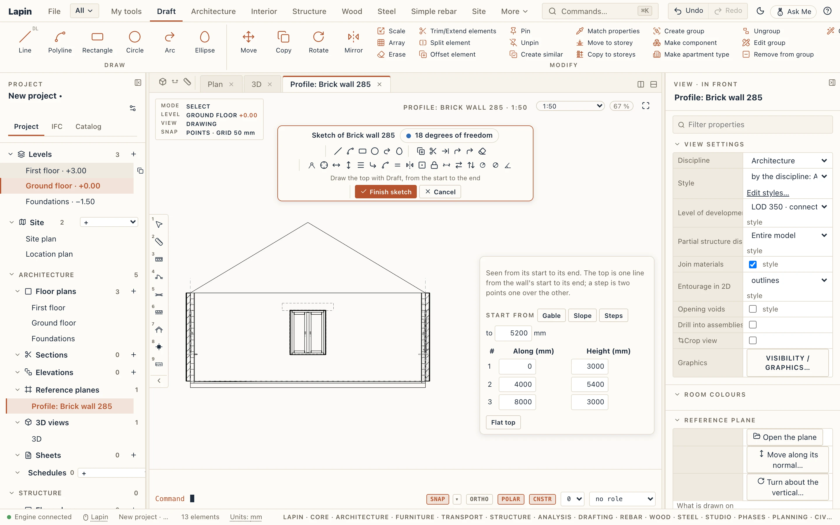
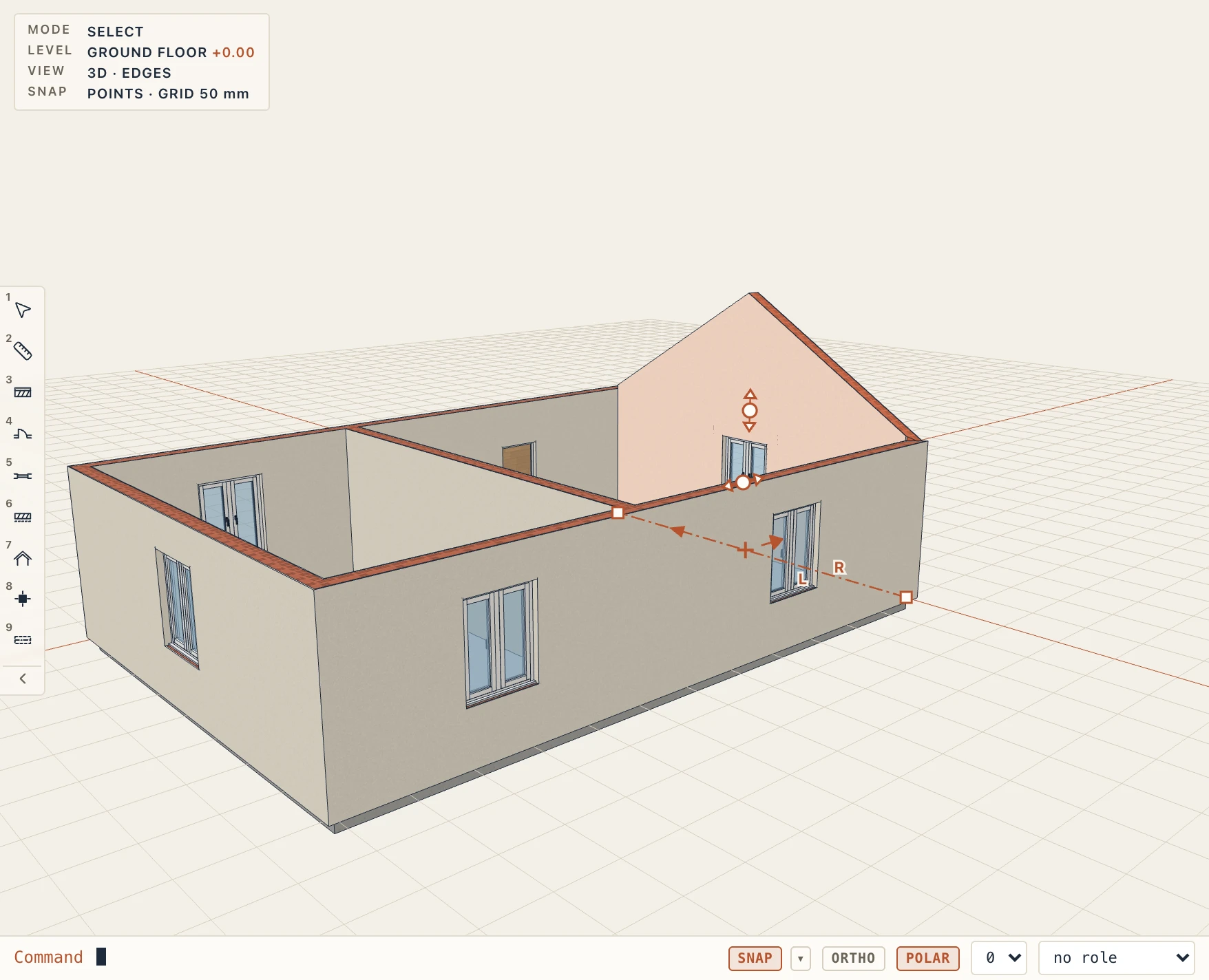
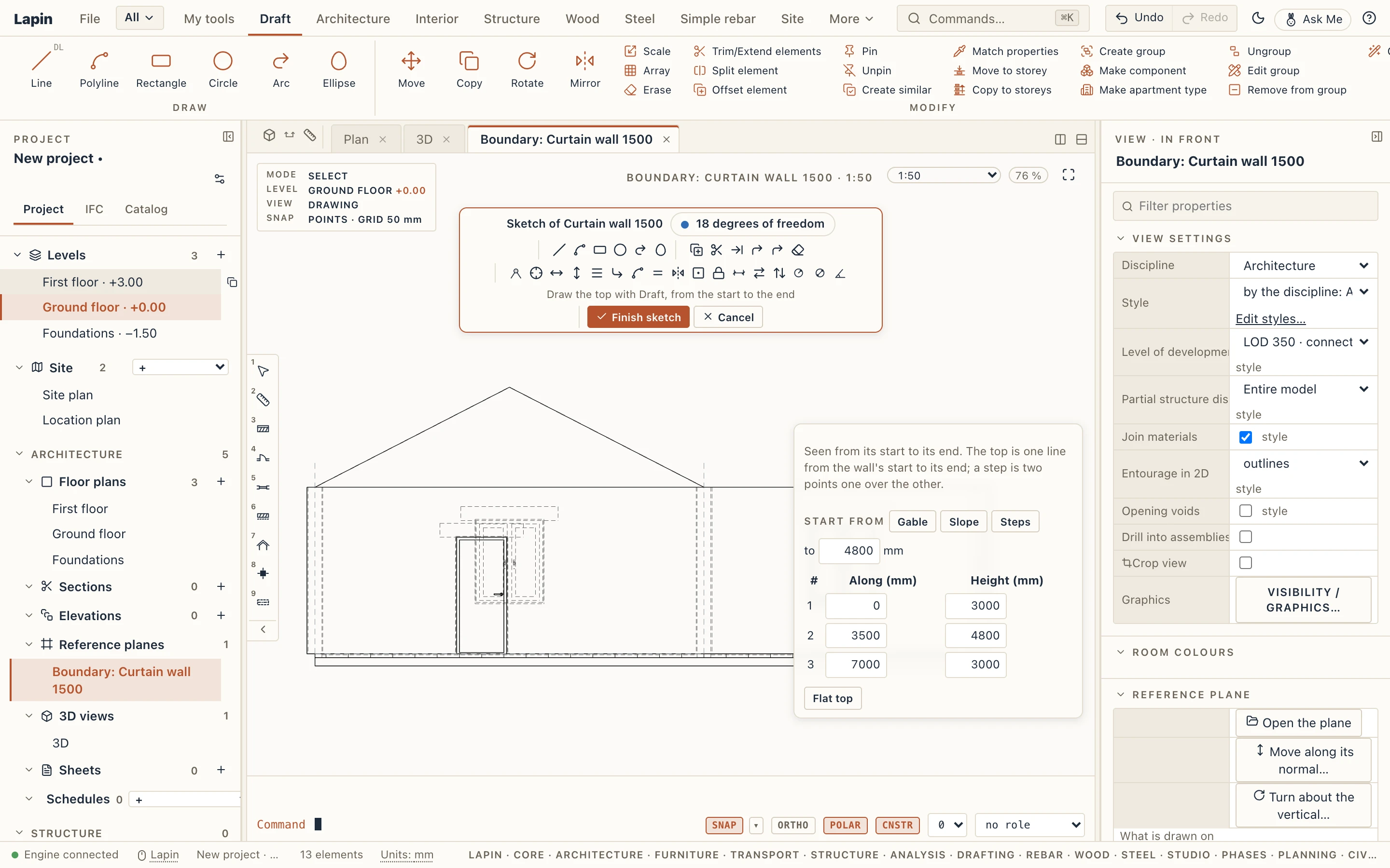
Profile… in a wall's properties opens its top on the sketch canvas: a view of its own standing on the wall's axis, seen from its start to its end, the wall hidden there and its base and ends drawn as construction lines. The top is one line from the start to the end: a gable, a slope, steps, a wall that follows a stair. Draw it with Draft's tools on the bar (Line, Polyline, Arc, Trim, Extend, Fillet…), move its points by their grips, snap to the levels and the other walls in the view, and hold it with constraints and dimensions as any sketch. The side form beside it starts from a Gable, a Slope or Steps up to the height you type, lists the top's points in millimetres to type over, and has Flat top. A step is two points one over the other; an arc is laid in short straight pieces. Finish sketch shapes the wall in one undo step; a top that turns back, is in pieces or runs past the wall's ends is refused with the reason, and the sketch stays open. Cancel leaves the wall as it was.
The wall stays a wall: its thickness, its layers, its joins and its doors and windows are as they were, and it exports to IFC with its shape.
A curtain wall's boundary and members
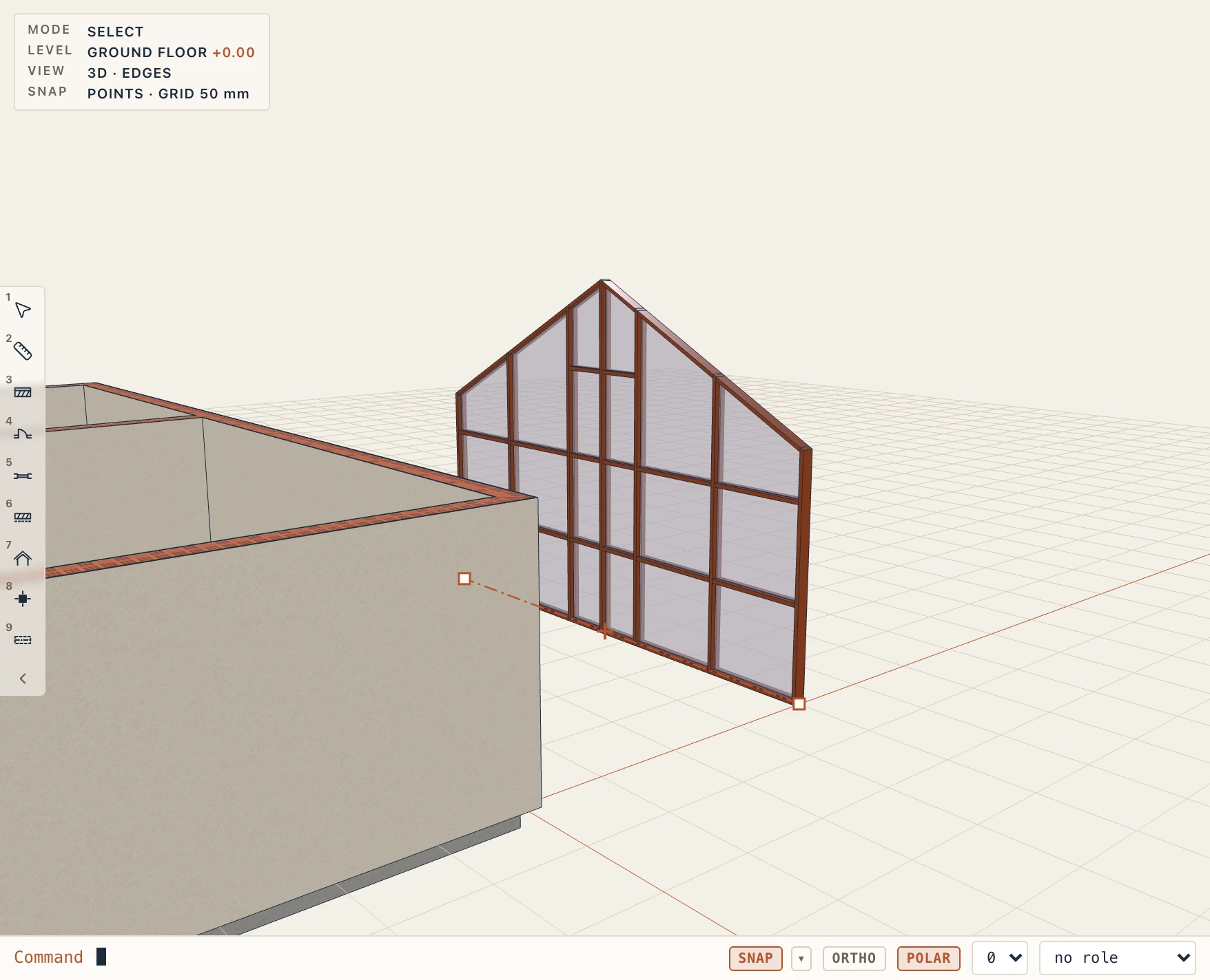
Profile… in a curtain wall's properties draws its boundary the same way, on a sketch of its own: a gable, a slope, steps, or any outline, with the same side form (a curved curtain wall keeps the profile dialog, with points to drag and a table in millimetres). The wall rises to its highest point. Its grid gains a line where the boundary bends (a bend within a mullion and a half of a grid line is moved onto it); each bay keeps the transoms that fit under its lowest point; the panel above the last one fills up to the boundary, and an edge member follows it, sloped; the mullions are cut to it. The type's settings stay, and Profile… opens the boundary again to change it, with no rebuilding; Flat top gives the rectangle back. It shows in 3D, elevations and sections, the schedules measure the panels and members as drawn, and the IFC carries them as parts.
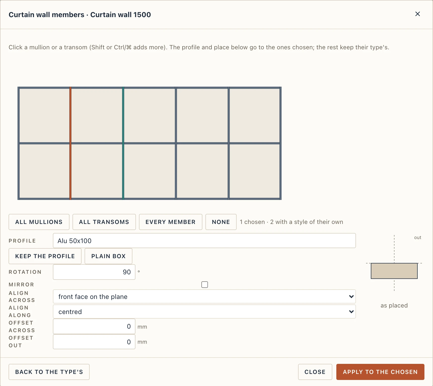
Members… gives chosen mullions and transoms a profile of their own. The wall's elevation shows every member: click one (Shift or Ctrl/⌘ adds more, or take all the mullions or all the transoms), choose a profile from the profile libraries or a plain box, its Rotation and Mirror, its alignment across the member (front or back face on its plane) and along it (start or end edge on the grid line or level), and its offsets across and out of the building; the picture beside shows the section as it sits. Apply to the chosen gives them the style, Back to the type's takes it off. A type's own profile has the same place fields in Curtain walls…, for every wall of the type. The profile stays a copy in the project: Update from the library changes every member made of it, in this wall and in others.
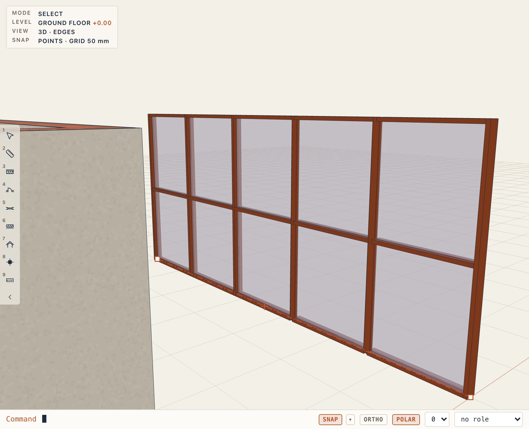
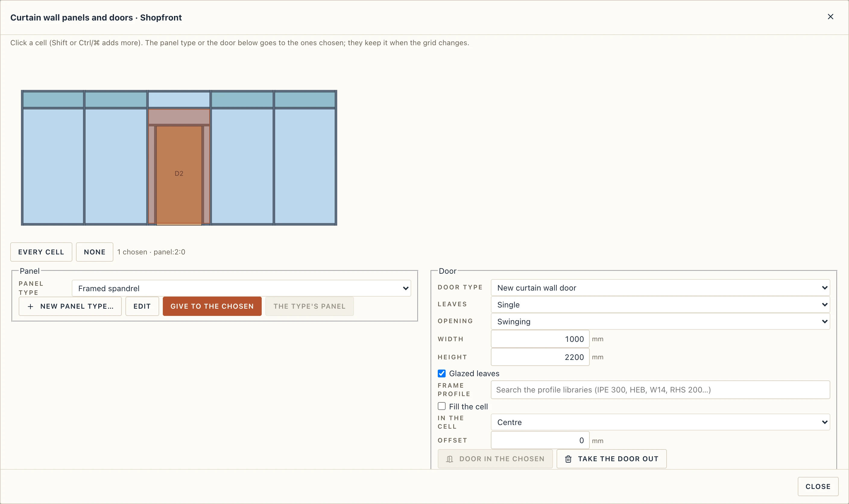
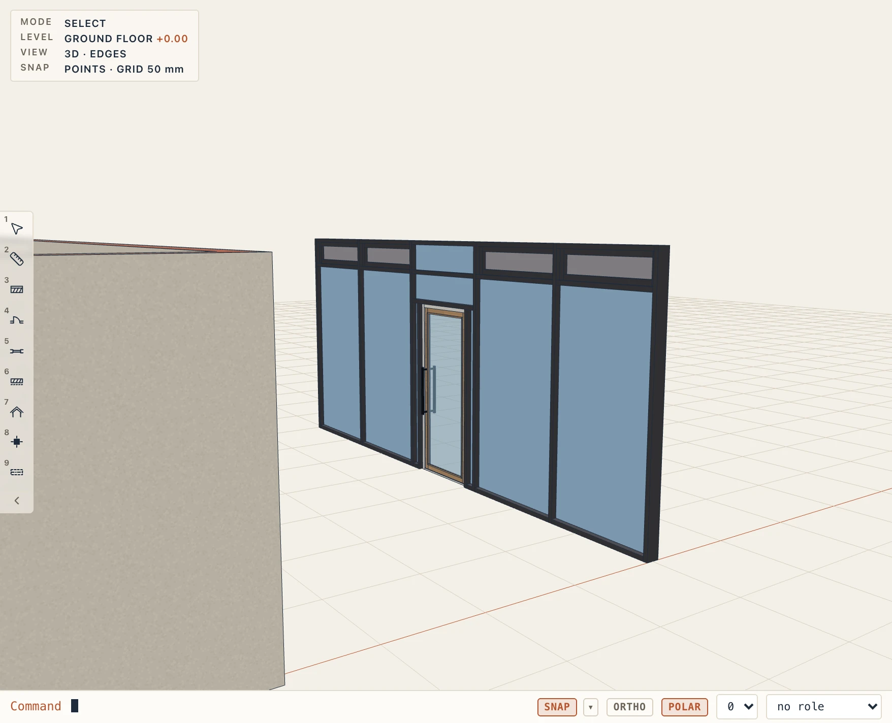
Panels and doors… gives chosen cells a panel of their own or a door. The wall's elevation shows every cell as the engine builds it: click one (Shift or Ctrl/⌘ adds more). A panel type is saved once in the project and given to cells of any curtain wall: glass, solid, a framed infill (a frame of its width and depth round the cell, the glass or solid infill set back from its outer face by the inset) or open (no panel); its thickness, its offset out of the axis and its materials (the curtain wall type's when none is chosen). Give to the chosen applies it, The type's panel takes it off; editing a panel type changes every cell of it. Door in the chosen replaces each chosen cell by a door: a new curtain wall door (single or double, swinging or sliding, its width and height, glazed or solid leaves, its frame profile from the profile libraries) or any door type of the project. Fill the cell makes it the cell's size; otherwise it keeps its type's, stands left, centred or right in the cell with an offset, and gets a transom over it and a mullion beside it where glass is left, glazed with the cell's panel. In the bottom row a door stands on the floor and the sill transom is cut away under it. The settings are kept by cell, so they follow when the grid changes: a door filling its cell grows or shrinks with it, and one whose cell is gone says so and comes back with it. The door is a door: select it to flip its hand or side, change its type, or move it to another cell (Move along the wall); tags, door schedules (at the size it stands) and the IFC export (an IfcDoor that is part of its IfcCurtainWall) count it.
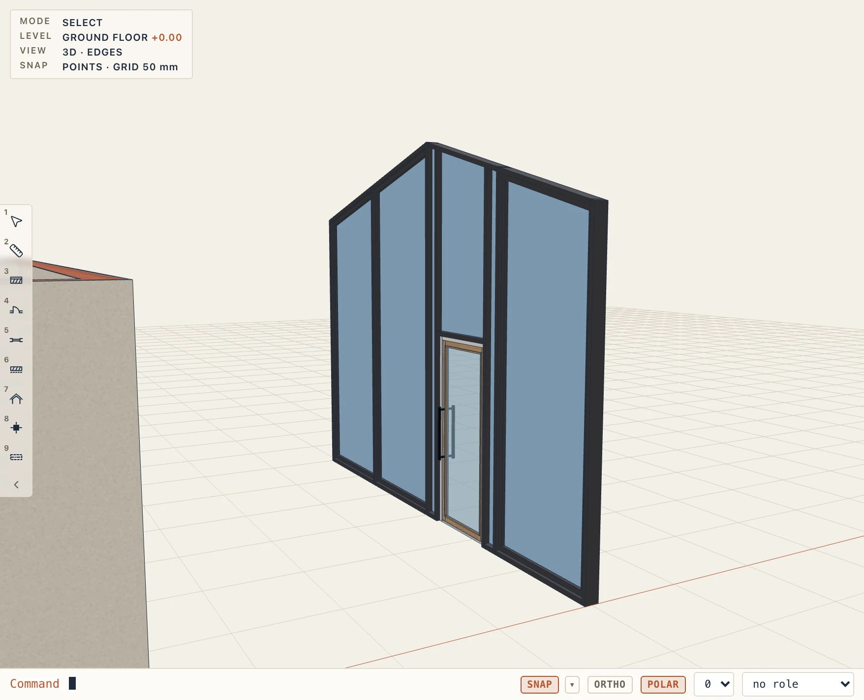
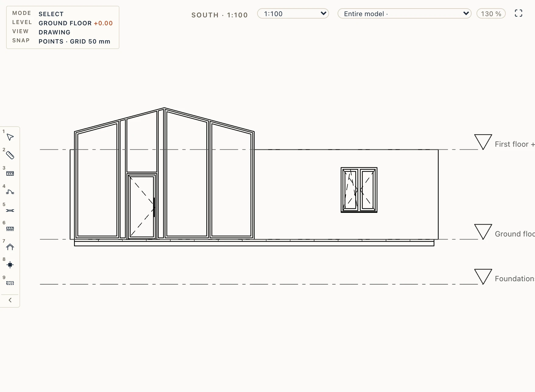
Under a boundary drawn with Profile… a door goes into a trimmed cell wherever its rectangle fits under the boundary: the mullions beside it rise to the boundary, the panes beside them fill up to it, a transom spans its head and the glass over it follows the slope. Filling such a cell, its head stops a transom under the boundary's lower side. Where it does not fit, Lapin says by how much and what to do (lower it, move it to the higher side, or choose a higher cell). A framed panel in a trimmed cell is framed along its outline, sloped side too. An elevation that faces a door's exterior draws its opening symbols, dashed, as for any door or window.
Layer extents
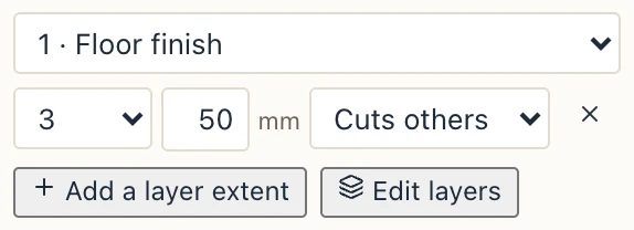
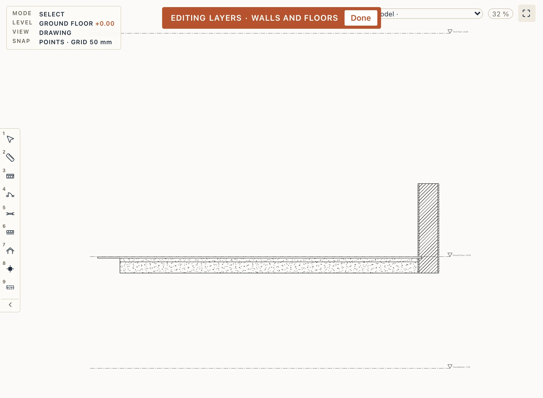
A wall's or a floor's layer can go on past the element's edge, or stop short of it, without splitting the element: a floor finish that runs 2 cm over the wall it was drawn to, a plaster that goes down past the wall's base into the floor's finish, a render that stops 10 cm short of the wall's top. Select the wall or the floor and open Layer extents in its properties. Add a layer extent adds a row: choose the Layer (numbered as in its type), the Edge and the Distance, positive past the edge, negative short of it (up to 1 m either way). A wall's edges are its Start, End, Bottom and Top, straight or curved (past an end of a curved wall the layer goes on along the end's tangent, as the wall itself does past its axis); a floor's are All round or one edge of its outline, numbered from its first corner (an edge's own extent wins over the all-round one). The × takes the extent away; an offset of 0 does the same. Each change is one step to undo.
The last choice of a row says what the part past the edge does where it meets another element: Overlaps (the two overlap and each keeps its volume), Cuts others (it is taken out of the wall, floor, column, beam or footing it meets: the wall loses the 2 cm the floor finish takes), or By cut order (it cuts only the elements its own comes before in Manage → Cut order: a floor's finish cuts the wall, a wall's plaster going down leaves the floor whole). Plans, sections, the 3D view, the quantities and the IFC export all show the element as it is built, layer sets kept; the extents travel in Lapin's own property set (Lapin_Intent), so a Lapin IFC file brings them back. When you move a corner of a floor, an edge's extent follows its edge; it goes away with an edge you take out. References from an IFC file have no layer extents: their bodies are their file's.
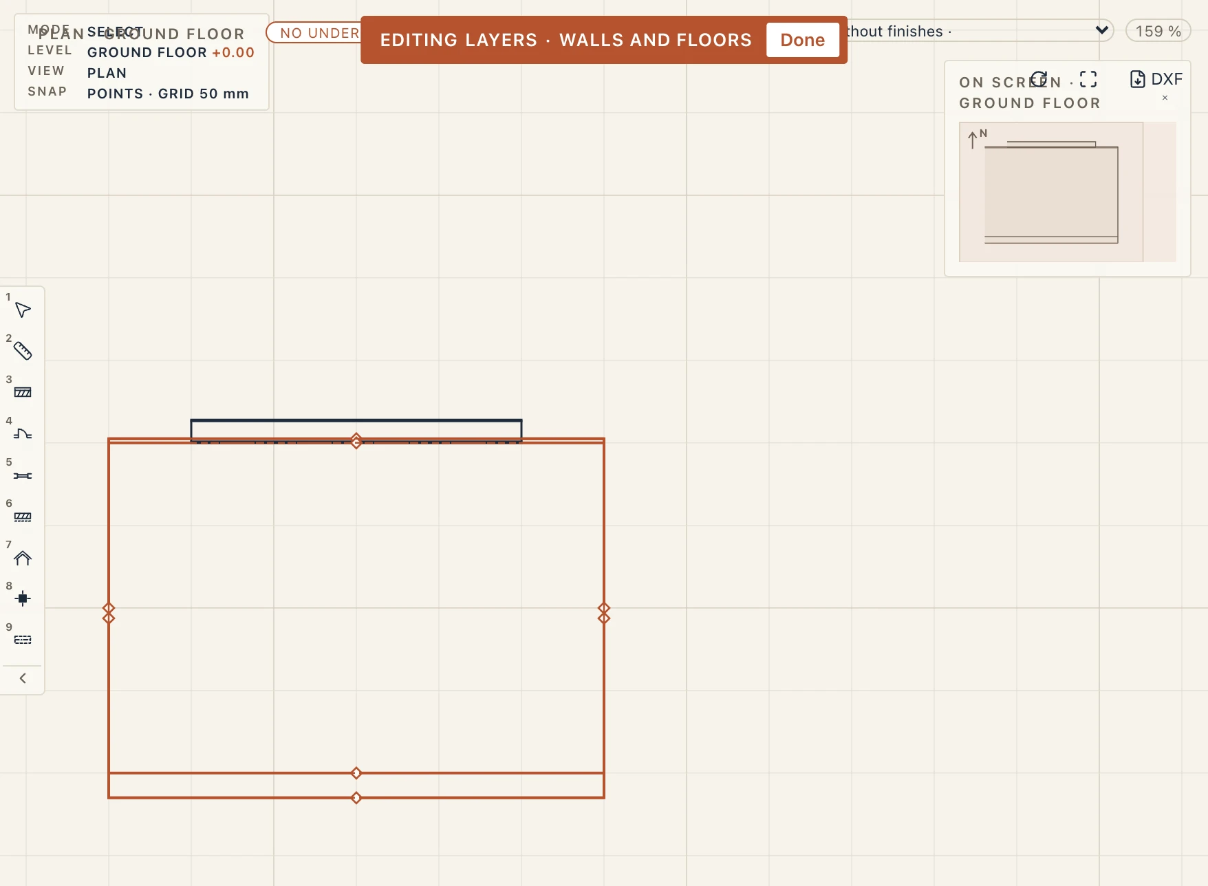
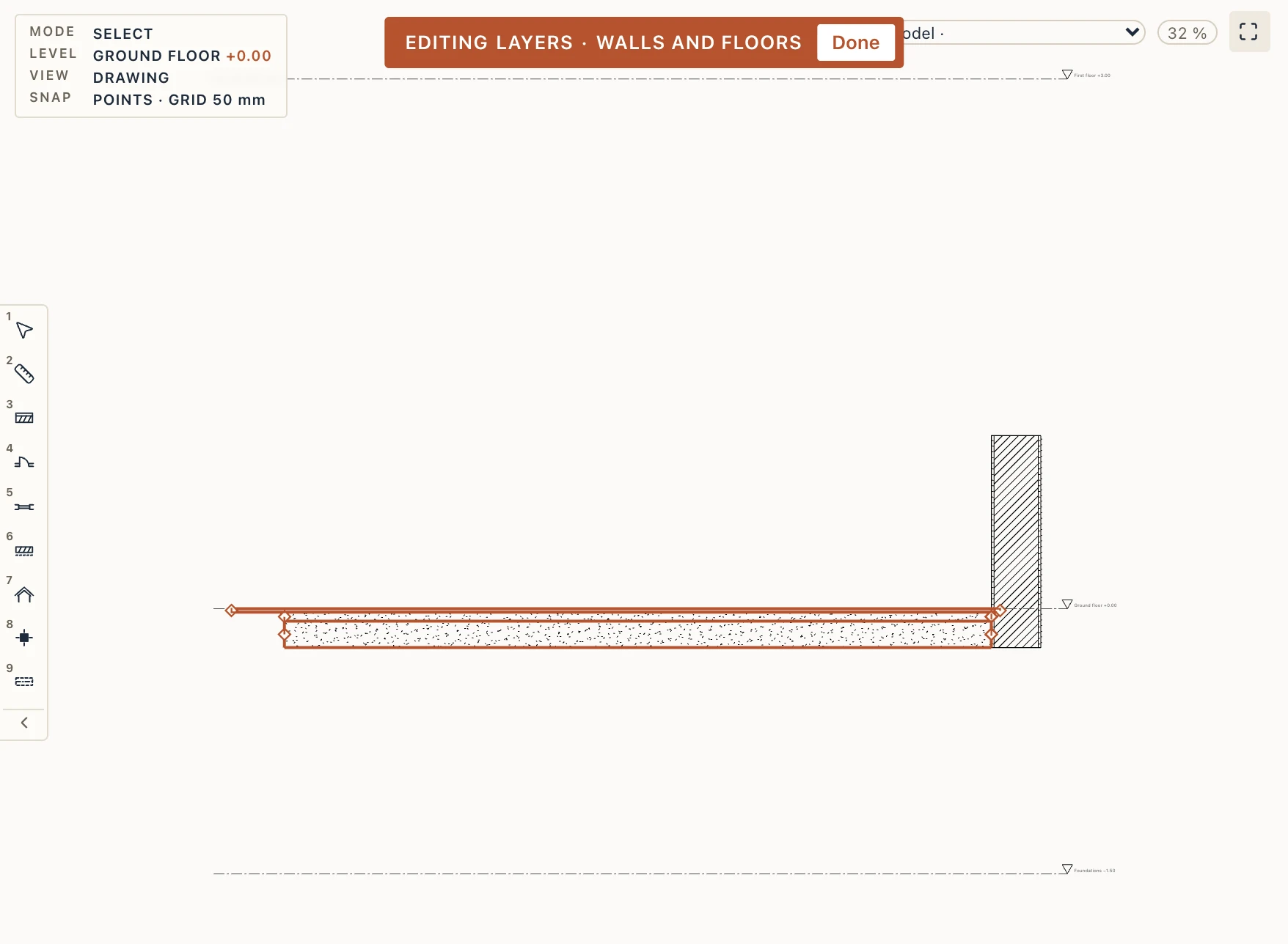
Edit layers (the button under the rows, or Architecture → Edit layers) drags the edges instead of typing them. In this mode a selected wall or floor shows each layer's outline, dashed, and a grip on each of its edges: in a plan a wall's ends and a floor's edges, in a section the edges the cut crosses (a wall's base and top, a floor's edges; a wall's ends where the section runs along it). Drag a grip out of the element or into it: it snaps as every grip does, and while you drag you can type the distance. Each drop is one step to undo. Done (or Esc) leaves the mode.
Under a roof a wall's layers go up to the roof; a Top extent moves the layer along the roof's line, 10 cm under it or 5 cm into it, the rest of the wall still cut by the roof. A wall type or a floor type can hold extents too (select the type in the project browser, its Layer extents in its properties): every wall or floor of the type starts with them, all round for a floor type. An element shows its type's rows marked From the type; changed there, a row becomes the element's own, which wins (an own 0 keeps that layer at its edge), and ↺ gives the place back to the type's.
Trimming, extending, splitting and offsetting walls
Modify → Trim/Extend elements (TRIMEXTEND, or TE, on the command line) works as Revit's does. First pick the boundary: a wall, a beam or a strip footing (its axis, or its face: answer N for the near face or F for the far one, A goes back to the axis), or a drafted line, a polyline segment, an arc or a circle. Then click the walls one after another, each on the part to keep: the end beyond the boundary is trimmed back, and a wall that falls short has its nearer end carried on to the boundary. A curved wall goes on round its circle. A wall brought to the axis of another wall is joined to it there. Doors, windows and openings keep their place in plan; one that would fall in the part cut away refuses. Enter finishes, Esc cancels. Each wall is one step of undo. The command line's TRIM and EXTEND also take a wall clicked in a plan.
Modify → Split element (SPLITELEMENT, or SPLIT) cuts a wall where you click it: two walls. The first keeps the id (its GlobalId in IFC) and the part from the wall's start; the second is a copy of it (type, storey, layers, properties, groups) and takes the joins at the far end. The two meet in an in-line join. Doors, windows and openings go to the part they stand in; one across the cut refuses (lies across the cut). Type I (Intersection) to pick the wall and then what crosses it, another element or a drafted line or arc, and cut there; P goes back to Point.
Modify → Offset element (the command line's OFFSET, which takes elements now): type the distance in the project's unit, click a wall in a plan, then the side to put the copy on. The copy is parallel to the wall, a curved wall's concentric, with the same type, layers and openings. A (Axis, the default) measures from the axis, F (Faces) from the wall's face, so that the copy's face stands the distance off it; T (Through) takes a point the copy goes through.
What hangs on the wall goes to the part it falls on. A finish painted on a straight wall's side stays where it was on the face; one whose region runs on across the cut paints the other part too, unless a split line of the face stops it, and one painted over the whole face covers every part. A sunshade along the wall goes to the part it runs along (one across the cut refuses, as a door does); a balcony goes to the part its middle is on, or stands free where it is when its part is cut away. Bars drawn in the wall are hosted by the part their point lies on, the formwork forms each part, and a timber-frame wall's own studs (see Wood) go with their part. A curved wall's finishes stay on its first part.
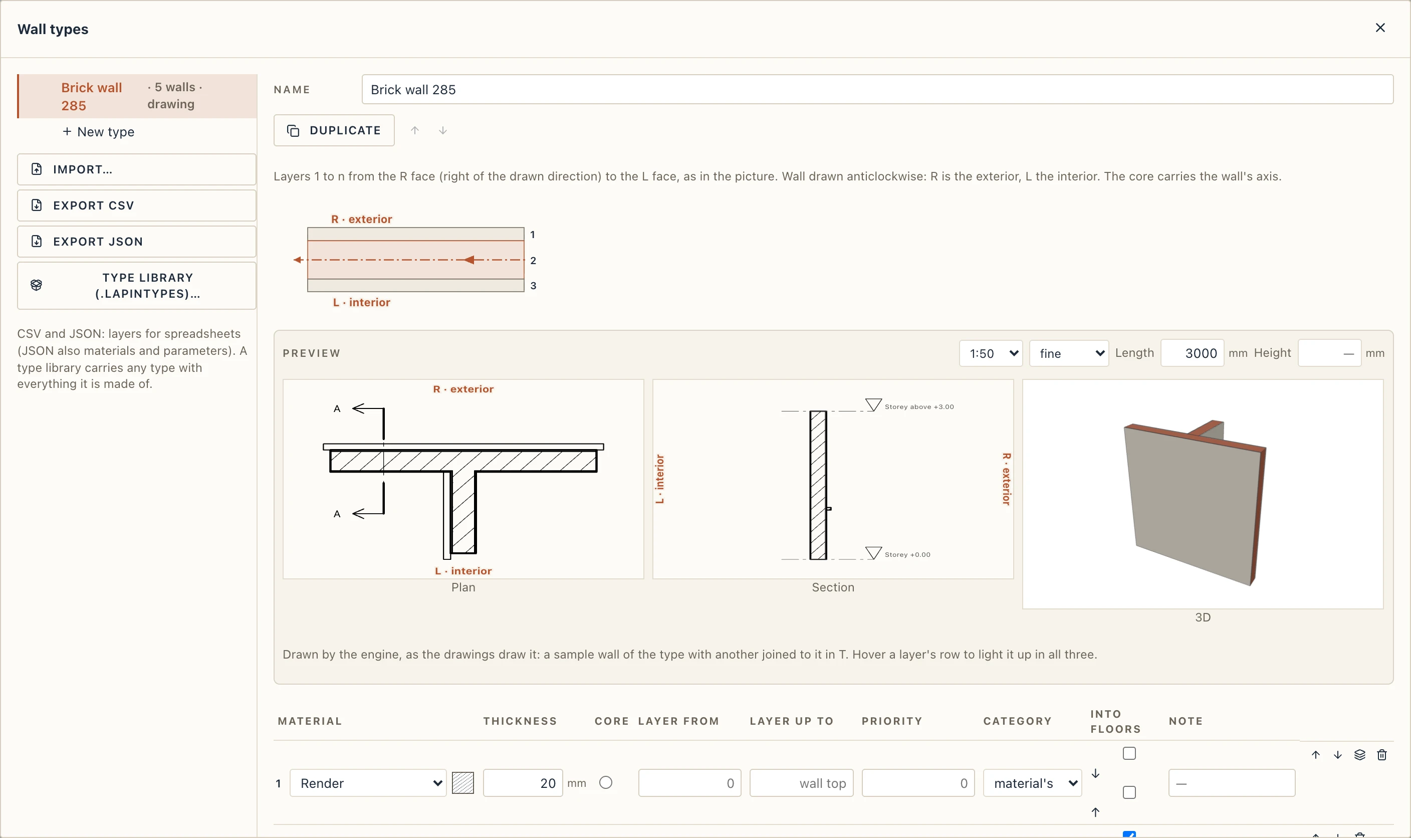
Wall types
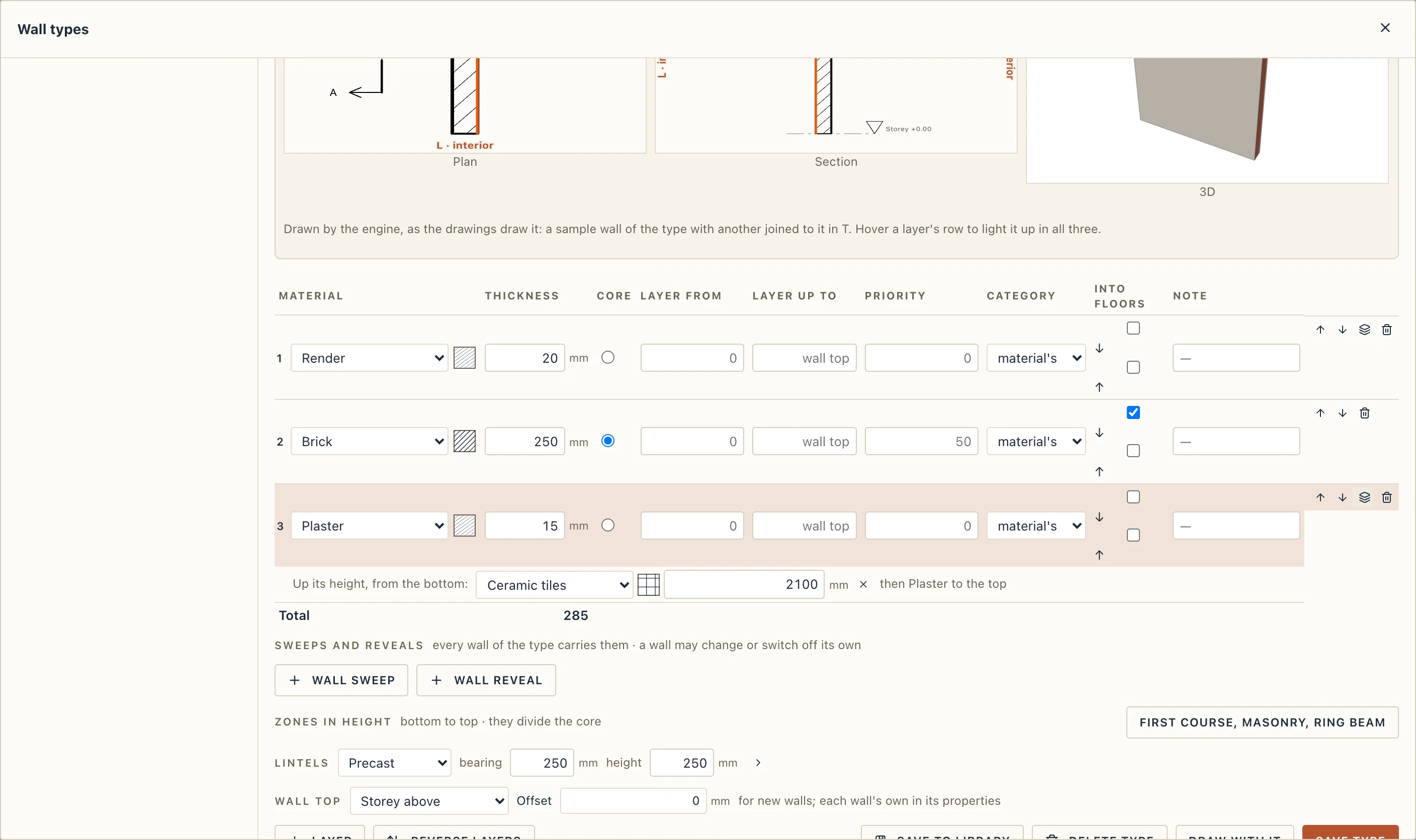
A wall type is a set of layers, from the face on the right of the way the wall is drawn (the outside, when you draw round a building anticlockwise) to the face on its left. Each layer has a material and a thickness, and one layer is the core. The wall's line runs along the core. To edit the types, choose Architecture → Wall types. A layer other than the core may have a height of its own: Layer from and Layer up to set how high the layer goes over the wall's base (not the wall's own top: the placeholder says wall top where it runs to the wall's top; a tiled dado up to 1500, a cladding from 300 up); empty, it runs the whole height.
Duplicate and order. Every type dialog (wall, floor, door and window, stair and ramp, column, beam and footing types) has Duplicate beside the type's name: it makes a type of its own with the same layers and settings, named „Name 2” (then „Name 3”…; „Brick 25 (2)” when the name ends in a number, so the number never reads as part of it), listed just after the original, ready to change without touching the first. The ↑ and ↓ next to it move the type up or down its list; every list and picker of those types (the properties panel's type, the tool's New element, the dialogs) shows them in that order, which the project keeps. Types never moved stay in the order they were made; a new type comes last. Each is one undo step.
The Priority column (0 to 100) says how the layer meets another wall's layers where the walls join: it goes on through the other's layers of a lower priority and stops at the first as high or higher. Empty, the layer takes its material's priority in Manage → Cut order, else 50 for the core and 0 for the other layers (the number shown greyed). So a concrete core of 100 is not interrupted by a stud core of 99 and runs through the stud wall, and a hard plaster of 60 holds the core of a wall ending on it. The IFC export writes it as the layer's Priority, and the import reads it back.
The Note column says how the layer is laid in this type (in a continuous layer, Baumit SupraFix): it belongs to the type, not to the material, and a build-up tag writes it after the layer; IFC carries it as the layer's Description. When the layer's material has catalogue thicknesses (Manage → Materials → Data), the small arrow beside the thickness offers them, and a warning sign marks a layer of another thickness.
A layer other than the core may also change material up its height: the layers button at the end of its row adds a piece (tiles, 2100 by default), from the layer's bottom up; add more for a band (paint to 900, tiles to 1500), and above the last piece the layer goes on in its own material to its top. Each piece is drawn, cut in plan and sections, and measured in its own material.
A layer other than the core may have a thickness of 0, for a material too thin to model but that must be measured: a waterproofing membrane, a vapour barrier, paint. It builds no solid; plans and sections draw it as a heavy dashed line where it lies between two layers (on a face, the face's line is its own), the Type assemblies build-up names it like the others, and it is measured by area: the side of the layer it lies on, net of openings, in the wall's quantities and the quantity takeoff by material.
The Category column says what the layer is in this type: Structure, Finish, Insulation, Membrane or Other. Empty (material's), the layer takes its material's category (Manage → Materials). A view style leaves the finishes out by it, so a cement board marked Finish goes with the plaster, and a plaster marked Other stays (see Views). IFC carries it as the layer's Category.
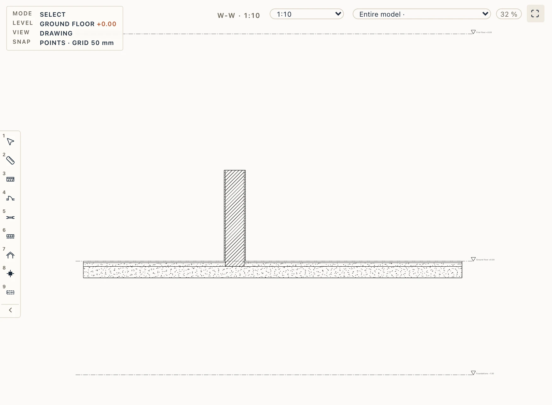
The Into floors column lets a layer go on into the floors' layers, as where walls join. With ↓ ticked, the layer goes down from the wall's base, through the layers of the floor the wall stands on that have a lower priority, to the top of the first layer as high or higher. By default the brick core (50) goes through the floor finish and the screed (0) and stands on the concrete slab (50). With ↑ ticked, the layer goes up through the lower layers of the floor above it (a ceiling plaster) to the underside of the first layer as high or higher. The floor loses what the wall takes, and the quantities of both follow. A floor layer's priority is set in Floor types. To make a plaster go down to the screed, give the plaster a priority above the floor finish's and below the screed's (for example a plaster of 10, a floor finish of 0 and a screed of 20). A new wall type's core goes down by default, and so does the default wall type a new project makes for its first wall, so it stands on the structural slab. Types made before stay as they were until you tick the boxes. Only straight walls go into the floors; curved walls stand on the floor as before. The IFC export writes the bodies as built, keeps the layer sets, and marks each such layer (Lapin_LayerJoins: ExtendToFloorBelow, ExtendToFloorAbove). The import reads the marks back.
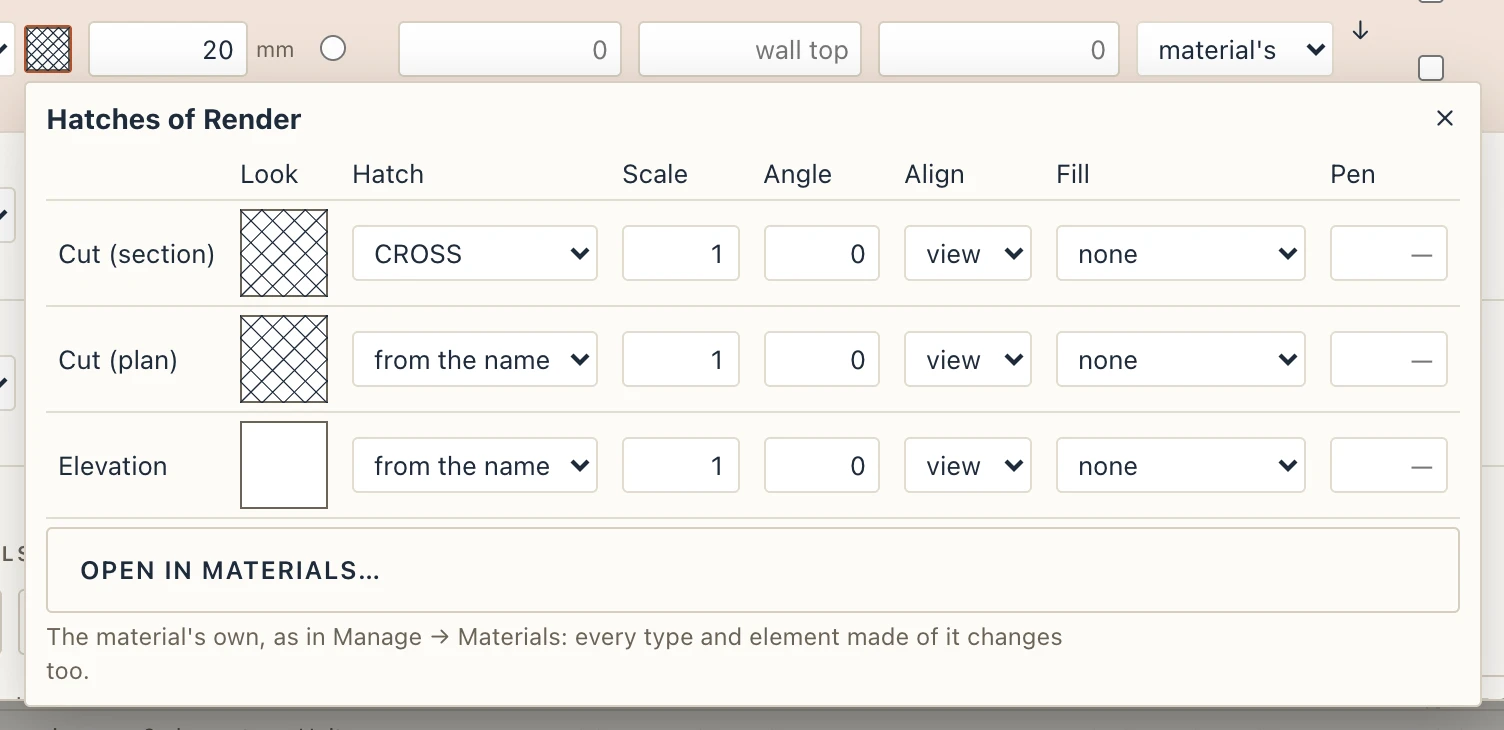
Hatches at hand. Beside each layer's material, a swatch shows how the material is hatched where it is cut. Click it to set the material's hatches there, without going to Manage → Materials: its hatch where a section cuts it, where a plan cuts it and where an elevation sees it, each with its scale, angle, alignment, fill and pen, as on the 2D graphics tab of Materials. They are the material's own, so every type and element made of it changes too, and each change is one step to undo. Floor types have the same swatch. A press outside it or Esc closes it. Open in Materials…, at the foot of the swatch's panel, opens Manage → Materials on that material's 2D graphics tab; what you have typed in Wall types (or Floor types) and not yet saved is kept, and Back to Wall types at the top of Materials returns to it as you left it.
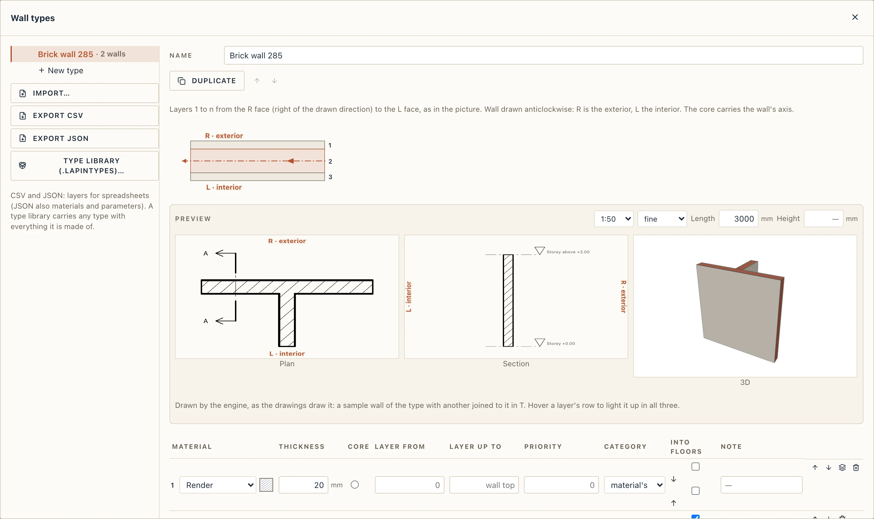
The legend above the layers shows the wall in plan, a section across it, the way a selected wall shows it: the dashed axis with an arrowhead the way it was drawn, R · exterior on top and L · interior at the bottom. The layers run as the rows of the table, top to bottom: layer 1 at the top, on the R face, to the last, on the L face, with the same numbers; the core, which carries the wall's line, is shaded. R is the face on the right of the drawn direction (where layer 1 goes), and it is the exterior when the wall is drawn anticlockwise round the building, as Lapin draws them; for a wall drawn the other way round, the faces swap. Reverse layers, beside + Layer, runs the rows the other way (the layer that was on R goes to L); Lapin asks first, because once the type is saved all its walls swap faces: what was exterior becomes interior. A wall turned with Flip has its layers the other way round, from L to R. A message from a save that was refused goes away as soon as you change the type again.
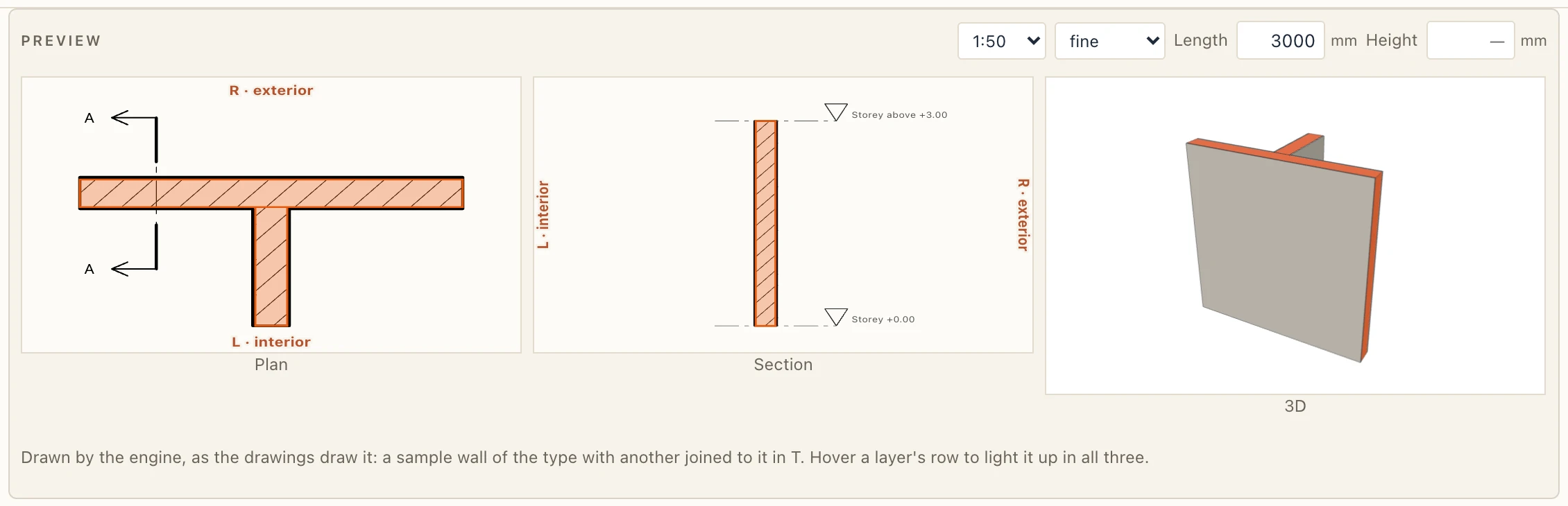
Preview. Under the legend, Preview shows the type as you edit it, before you save it, the way the drawings will show it: a sample wall of the type, 3 m long, with a shorter wall of the same type joined to its middle in T, in Plan, Section and 3D side by side (one at a time, with tabs, when the dialog is narrow). Lapin builds the sample as it builds any wall, joins and layer priorities included, and draws the plan and the section as it draws a view: with the project's hatches, pens and view styles, at the View scale (1:20, 1:50 or 1:100) and the Detail level (coarse, medium, fine) chosen above the panes. In the plan, R · exterior is on top, as layer 1 is in the table; in the section, R is on the right. Move the mouse over a layer's row and that layer lights up in all three. Length and Height set the sample's size; with no height, the sample goes up to the storey above, or as the type's Wall top says. The 3D turns with the mouse and zooms with the wheel. The preview is made apart from the project: nothing is added to it and there is nothing to undo.
- + Layer adds a layer. The arrows move a layer up or down.
- Zones in height splits the core from bottom to top, for example a first course, the masonry and a ring beam.
- Lintels chooses the lintels set over doors and windows: precast or cast in place, with their bearing and height. A precast lintel can be a beam type of Structure types, its section, lengths, material and bearing taken from it (see Beam types as lintels).
- Draw with it closes the dialog and starts drawing walls of this type.
A change to a type changes every wall of that type.
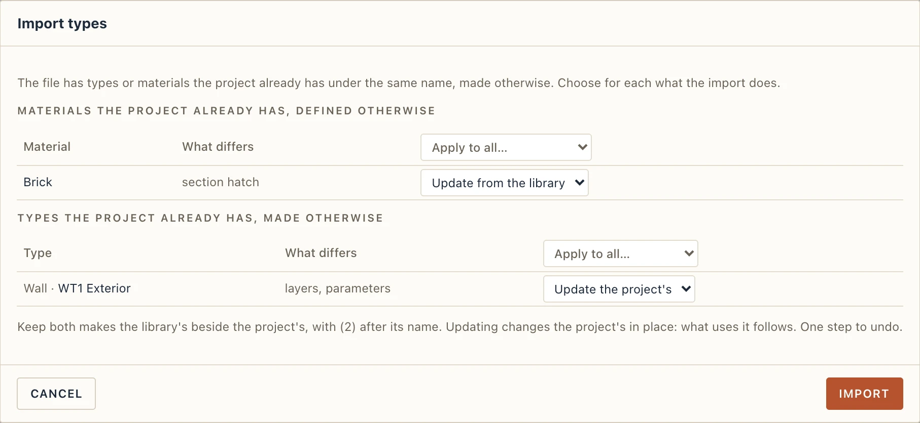
Import…, Export CSV and Export JSON, under the list of types, take the wall and floor types out of a project and into another, or into a spreadsheet and back: the CSV has one row a layer (Kind, Type, Mark, Layer, Material, Thickness (mm), Core, From, To), a type's rows one after another, and Excel's semicolons and decimal commas are read too. Brought in, a type of the same name is changed to the file's layers and any other is made, in one step to undo; a material the project lacks is made by its name. The JSON carries more than the layers: each type's parameters (its IFC properties, such as Pset_WallCommon.FireRating and IsExternal, and sets of your own) and the whole definition of every material its layers use (colour, the cut, plan and elevation hatches with their scale, angle, alignment, fill and pen), so the other project makes them as they were. When the file has a material or a type the project already has under the same name and defined otherwise, Lapin lists them before importing, with what differs (section hatch, colour, layers, parameters…), and you choose for each: a material Keep the project's (the default), Update from the library (changed in place: everything that uses it follows) or Keep both (the file's is made as Name (2) and the imported types use it); a type Update the project's (the default: its walls follow), Keep both or Skip. Apply to all… sets one choice for the whole column. What the import did (types made, changed, skipped; materials made, updated, kept) is listed under the buttons, and a failure is always shown. Importing into a project with no wall type at all works the same, and the first type brought in opens in the editor. The CSV stays a spreadsheet's: layers only. Type library (.lapintypes)… opens Manage → Type packs…, for a library of any kind of type (walls, floors, roofs, doors, windows, columns, beams…) with everything it is made of: see Extensions.
A type's parameters are in its properties (select an element of the type: Type parameters), and in Wall types under Parameters. A new type takes them before it is made: add them under Parameters (a name and its kind, or Add a standard property… such as Pset_WallCommon · IsExternal), set their values, and Create type makes the type with them in one step to undo, so every wall drawn with it has them from the start.
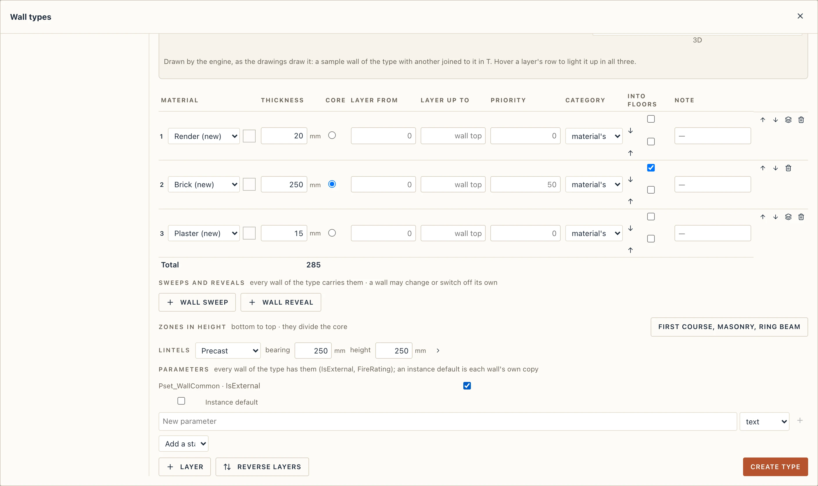
A parameter the type has for itself, such as a fire rating, is shared by every element of it and goes to IFC on the type. Tick Instance default for one each element should have of its own, such as a renovation status (new, existing, demolish) or a room's use: every element given the type afterwards (drawn with it, or changed to it) gets a copy in the same step to undo, which you can then change on the element, and IFC writes it on the elements, not on the type. Elements placed before keep what they had until you press Apply instance defaults to elements of this type, which gives each one the defaults it lacks (an element's own value stays). Phases also give IFC each element's Status (NEW, EXISTING, DEMOLISH, TEMPORARY) in its common property set, unless you set one yourself.
The Type assemblies schedule (Schedules → + → Type assemblies) lists every wall and floor type with its mark, its total thickness, how many elements use it, and its layers in order.
Wall sweeps and reveals
Architecture → Wall sweep (WB) runs a profile along a wall's face: a cornice, a band, a plinth, a sill. Wall reveal (RV) cuts one into the wall: a groove, a shadow gap. Choose the profile and the height in the command line's bar, then click the wall's face. In 3D the sweep goes at the height you click; in a plan it goes at the height typed, on the side you click. from the top measures the height down from the wall's top, for a cornice under the eaves. Sweep on selected walls and Reveal on selected walls put the same on every wall selected, on its exterior face.
A sweep runs the face's whole length and stops at the doors and windows it would cross. Where two walls meet in a corner and both carry a sweep of the same profile at the same height on the faces that meet, the two are mitred into one another, one moulding round the corner. Select a sweep to change it in Properties: its profile, its material, its face (Flip side), its height, its offset from the face, where it starts and ends along the wall, and whether it stops at openings. A wall's properties list the sweeps and reveals it carries.
Sweeps and reveals go with their wall when it is copied, moved to another level or deleted. They are measured by length and volume (for a reveal, the volume taken out). In IFC a sweep is an IfcCovering MOLDING and a reveal an IfcOpeningElement RECESS in its wall; both come back as they were.
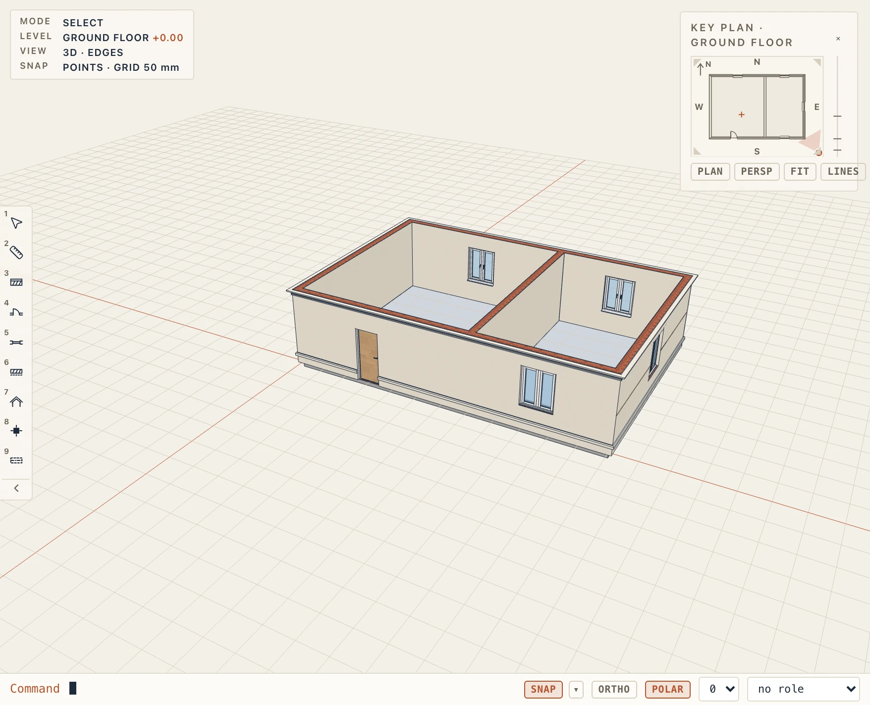
Sweeps on the wall type
A sweep every wall of a type should carry (a plinth band, a cornice, a shadow gap) belongs to the type. In Architecture → Wall types, under the layers, Sweeps and reveals lists them, one row each: the profile, Wall sweep or Wall reveal, the face (R, the face of the type's first layer, or L, as the legend names them), the height over the wall's base (or under its top with From the top), the offset out from the face, a sweep's material and its returns. Wall sweep and Wall reveal under the table add a row. Save the type: every wall of it gets them, and so does a wall drawn with the type or changed to it. They are sweeps like the others: measured, listed in the Wall sweeps schedule, mitred round the corners where walls of the type meet, written to IFC. A flipped wall's sweeps change face with its layers. Export JSON under the list of types carries them, with the profiles' outlines and the materials by name (the CSV has only the layers).
Select one on a wall: Properties says From the type. Change its height, its offset or any other of its fields and that field becomes the wall's own (Own: height): later changes to the type leave it as it is. Back to the type gives it the type's values again. Switch off on this wall, or deleting it, leaves the type's sweep off that wall; Switch the type's sweeps on again, in the wall's Sweeps and reveals, brings them back.
Returns
A sweep that reaches a free end of its wall (no wall joined there) returns: mitred at the end, its profile turns round the corner onto the end of the wall and stops in the plane of the face, so the moulding is closed instead of showing its cut. Returns at free ends in Properties chooses both (the default for a sweep), at the start, at the end or none, for square ends. A reveal never returns. At a corner joined to another wall a sweep does not return: it runs to the corner, or into a like sweep on the other wall. At doors and windows it stops square; tick Returns at openings to return it round the jambs as well. Set back from the start and Set back from the end stop it short of the face's ends (square there), and Profile upside down turns its profile over.
Moving and copying a sweep
Select a sweep and use MOVE or COPY as for any element; its wall stays. What the move goes along the wall slides the sweep along it (a sweep along the whole face then gets its own start and end); what it goes across the wall is left out. Moved up or down in an elevation or a section, its height changes. A copy lands on the same wall, shifted, or on another wall when it lands inside it, on the face it lands on. ROTATE and MIRROR keep it on its wall: mirrored across the wall's axis, it goes to the other face. A sweep of the type you move keeps its new place as its own; moved onto another wall, it becomes that wall's own sweep and the type's is switched off on the first.
Profiles
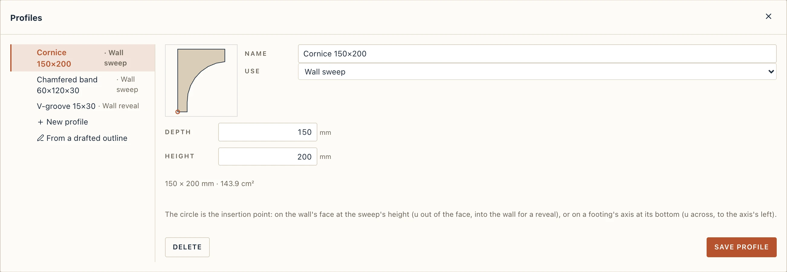
Manage → Profiles holds the project's profiles, the outlines that sweeps, reveals and strip footings are swept with. New profile starts from the catalogue with its sizes: a rectangle, a chamfered band, a cornice, a half-round, a sill nose, a band with a drip; a V-groove, a rectangular or a round groove; for footings, rectangular, stepped in 2 or 3 steps, with a sloped top, eccentric, with a stem. Or choose Typed corners: each corner u v in millimetres, a semicolon between them, a third number to make the side from that corner an arc. From a drafted outline reads a closed polyline or rectangle drawn with Drafting and selected in its view. The circle in the preview is the insertion point: for a sweep it lies on the wall's face at the sweep's height, u going out of the face (into the wall for a reveal). Change a profile and everything that uses it follows.
Cladding
Model cladding with the wall's own layers, not with sweeps. Add a finish layer on the outside of the wall type (stone, timber boards, fibre cement, an ETICS), with its thickness and material. Layer from and Layer up to give it a height of its own (a stone plinth up to 600, render above it), and the layer's layers button changes its material in bands up its height. For cladding that stands apart from the wall, draw a wall of its own on the face (the wall tool's line option Exterior face) with a type made of the cladding's layers. Cladding laid board by board (vertical or horizontal boards, battens) is not modelled yet.
Walls under a roof
Walls on the same level as a roof stop under it by themselves and rise to its gables. For a wall on another level, select it and choose Architecture → Attach to roof (AR), then click the roof — or any other body the wall should rise to: a Studio solid, an imported element. See Floors and roofs.