User guide
The site and its data
Bring the survey, the parcel, the neighbours and an orthophoto in real coordinates, from DXF, CSV, GeoJSON, CityJSON and a georeferenced image.
The Site tab holds the ground the building stands on: the terrain, the parcel, the neighbouring buildings and an aerial photo, each where it really is. The Import group brings them from the files surveyors and the cadastre hand over.

Real coordinates
A survey comes in map coordinates: eastings and northings, hundreds of kilometres from zero. Lapin keeps the model near its origin and ties it to the map through the survey point. The first import into a project does this for you: the survey point goes to the plan's origin, on the file's first coordinates rounded to the metre, and every later import lands in the same place.
Manage → Location shows the coordinate system the eastings and northings are in, and the base and survey points. Lapin knows Stereo 70 (EPSG:3844, Romania's national grid), UTM zones 34 and 35 (EPSG:32634, 32635), Web Mercator (EPSG:3857) and longitude and latitude (WGS 84, EPSG:4326). A file in another of these systems is converted when it comes in: a GeoJSON in longitude and latitude lands on the Stereo 70 plan where it belongs. Lambert-93 (EPSG:2154, France's national grid) is known too.
Latitude and longitude. The base point can also take its Latitude and Longitude (WGS 84, in degrees). With a projected coordinate system and no survey point, they tie the project to the map by themselves: Lapin works out the base point's eastings and northings in that system, and the plans, the spot coordinates, the DXF in map coordinates and the exports use them as they would a survey point's. A survey point you set comes first.
On the map in other programs. The IFC export writes the project's tie to the map as buildingSMART's guide to georeferencing asks: an IfcProjectedCRS named by its EPSG code (EPSG:3844…) with its datum, projection, zone and the metre, and an IfcMapConversion with the eastings, northings and height of the internal origin, the turn to true north and a scale of 1, so a GIS program, Bonsai or a viewer places the model where it is. IfcSite carries the base point's latitude, longitude and elevation. A project with a latitude and longitude but no projected system is written in the UTM zone of its place, and the export says so; a project with none of these writes nothing of the map. An IFC with a map conversion (IFC4 and IFC4X3, or IFC2X3's ePSet_MapConversion and ePSet_ProjectedCRS) ties a project that is not yet tied when it comes in, and a site's latitude and longitude alone become the base point's.
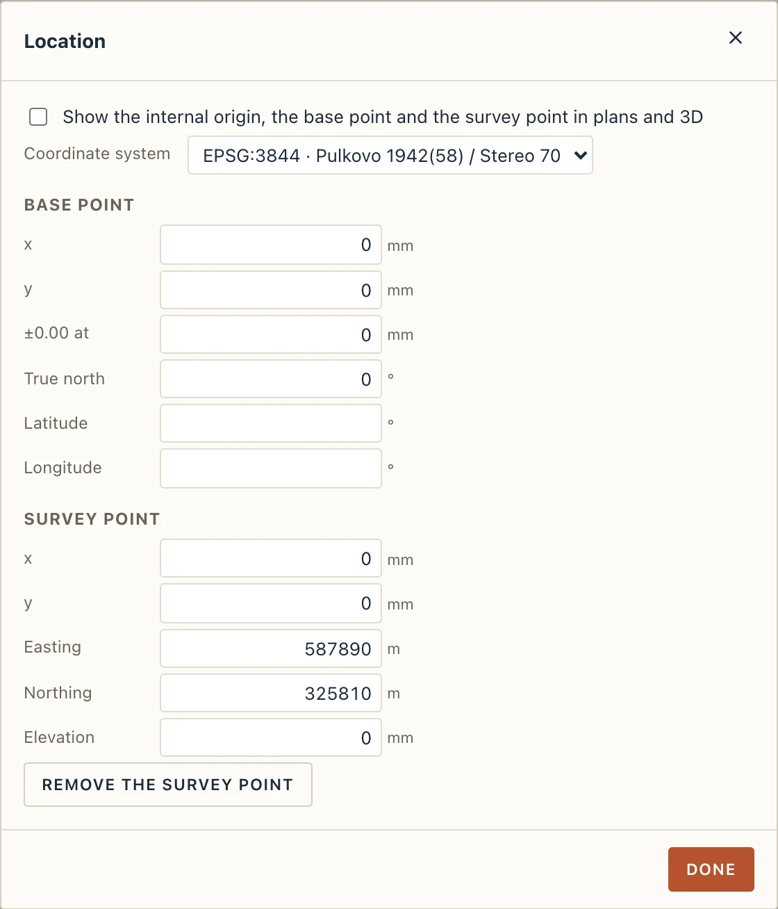
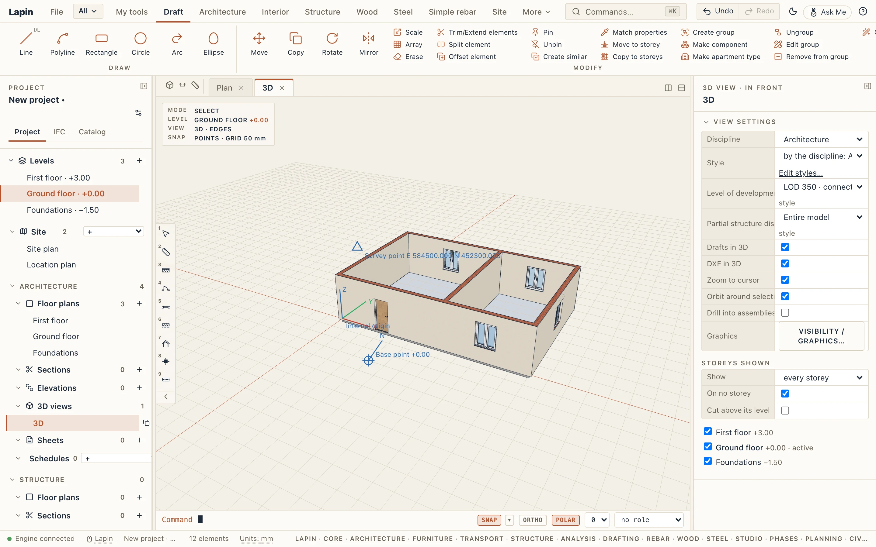
The project's points, as in Revit. View → Coordinate points (or Show the internal origin, the base point and the survey point in plans and 3D in Manage → Location) draws three points in plans and in the 3D view:
- the internal origin, the plan's 0,0, which never moves: its X axis in red and its Y axis in green (and Z in blue in 3D);
- the project base point, a circle with a cross: its elevation (where ±0.00 stands), its map coordinates when the project is tied to the map, and an arrow to true north with its angle when the project is turned from it (True north in Manage → Location);
- the survey point, a triangle, with its eastings, northings and elevation.
A plan snaps to all three. The 3D view draws them at their places at any zoom, over the model.
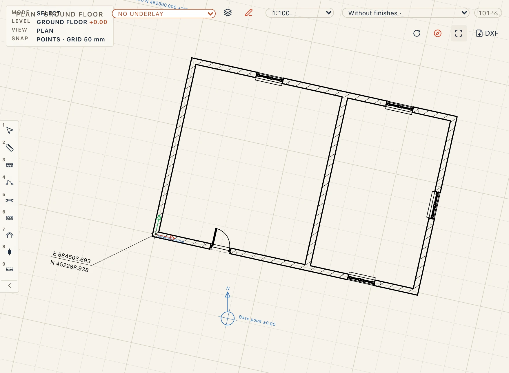
Coordinates at the cursor. While the cursor is in a plan, the status line reads where it is. A click on the coordinates chooses what they are read from: the internal origin, the project base point, the survey point (map) (eastings and northings, turned to true north, as the IFC export writes them) or the UCS (see Snaps and helpers). The choice is kept in File → Preferences… → Coordinates.
Plans of a georeferenced project. The model is drawn in its own coordinates, near the internal origin; the map's are worked out from the survey point, so a plan stays as precise and as quick as any other. Three things put it on the map:
- Spot coordinates. Annotate → Dimension, set to Spot coordinate in its bar (DIMCOORD): click a point, then where its leader ends. It writes the point's E and N in metres, through the survey point and turned to true north; without a survey point, its X and Y from the project base point. Type M, P or I first to choose the map, the base point or the plan's origin. The values are worked out on every drawing: move the survey point and every spot coordinate is written again.
- A plan in map coordinates. The plan's DXF button exports it in the plan's coordinates (millimetres from the internal origin), from the project base point (millimetres) or in map coordinates (E and N in metres, turned to true north), so the drawing lands on the cadastral plan or the surveyor's DXF.
- True north up. When the project is turned from true north, the compass button in the plan's bar turns the plan on screen so true north points up, and back. Drawing, snaps, the grid and the UCS turn with it; the choice is kept for each plan on this computer. Sheets and the PDF keep project north up. To print a plan turned, use Rotate view → True north up instead (see Rotating a plan): the orientation is the view's, kept with the project, and its sheets print it as it shows.
Importing
- Terrain from points reads a CSV or text file from a survey: x y z, or number northing easting elevation, one point a line.
- Points from DXF reads a survey drawing: POINT entities with their heights, blocks inserted at a height or carrying it as an attribute, heights written beside points ("245.37" next to its cross), and contour lines at their elevation. When the drawing has points on several layers, Lapin lists them with how many points each holds, and you choose which to take. The points make a terrain. A DXF names no system, so Lapin takes numbers the size of a map's by their range (Stereo 70, Lambert-93, UTM). Numbers of a system it does not know are kept as they are, and Lapin says so: name the system in Manage → Location, or convert the drawing first.
- GeoJSON brings parcels, lines and points. A file with one polygon gives the parcel; one with several gives areas. The parcel also outlines the terrain's parcel, with its area. Files from the cadastre in Stereo 70 say so in the file, and Lapin reads it; a file that says nothing is longitude and latitude, as the GeoJSON standard requires.
- CityJSON brings the neighbouring buildings with their surfaces, at their place and height. They are read-only references; they will cast shadows in the sun study.
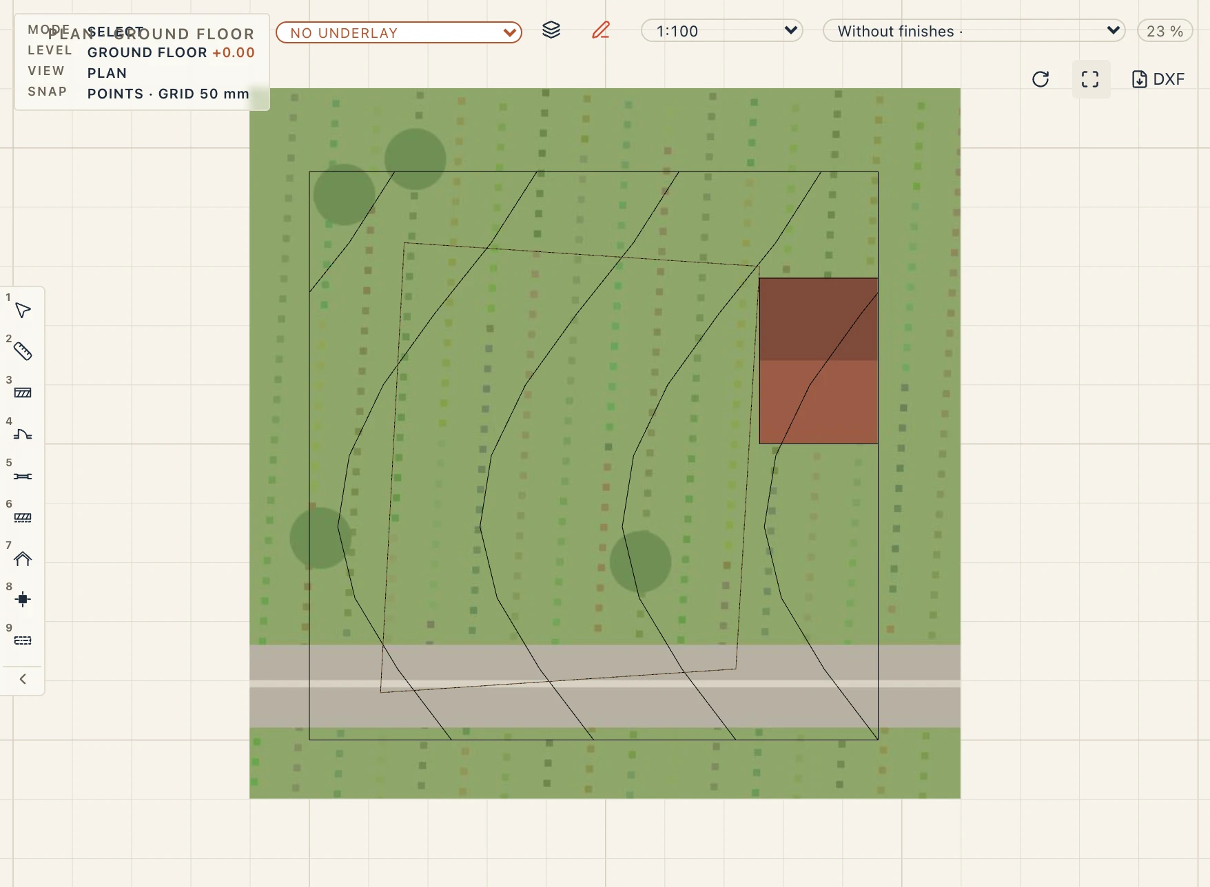
- Orthophoto lays an aerial photo under the site. Pick the image (JPEG or PNG, up to 8 MB) together with its world file (
.jgw,.pgwor.wld): the world file says where the image lies. The photo is drawn under the plan and wears the terrain in 3D.
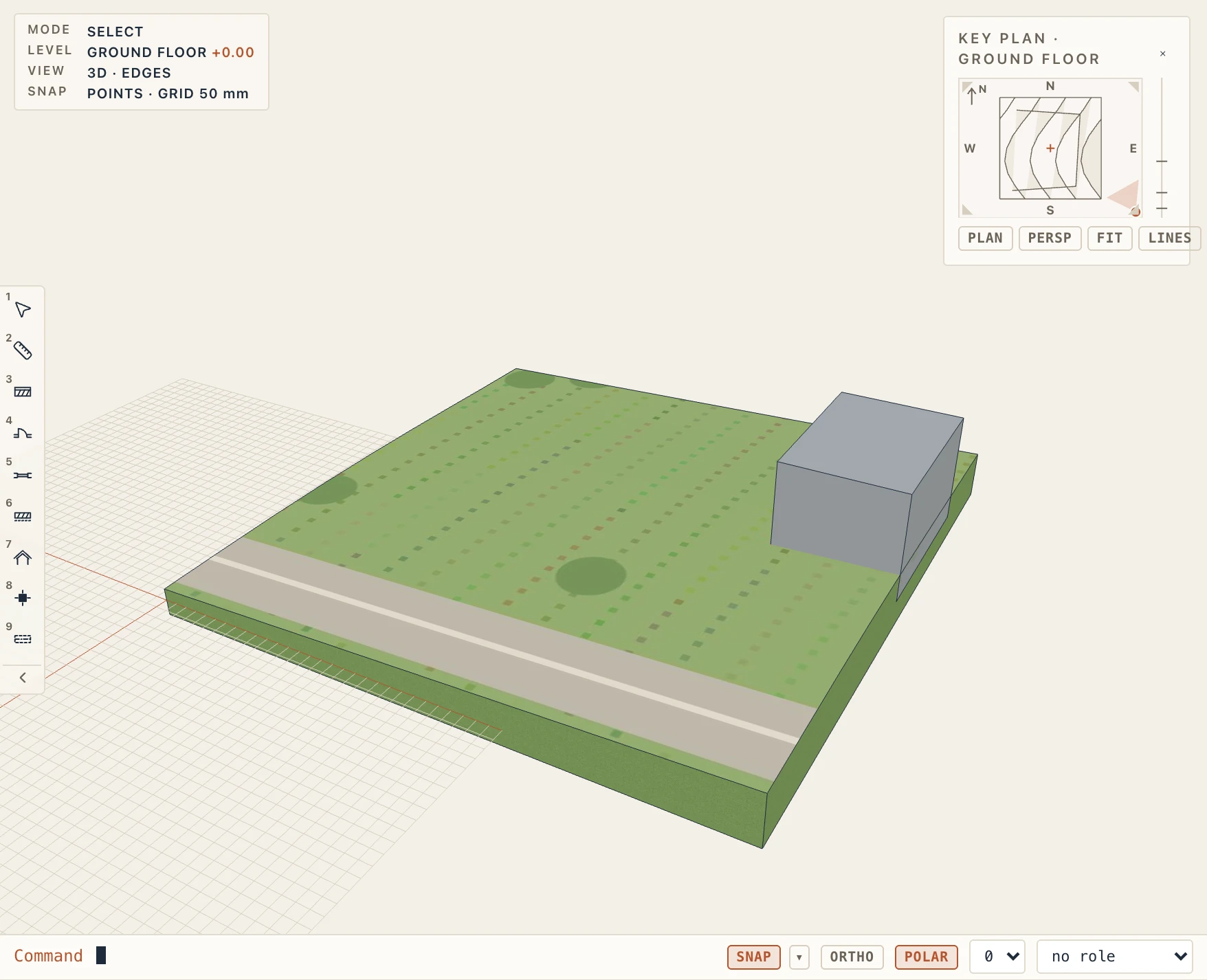
Everything imported is kept in the project file. A feature takes its name from the file (a parcel's cadastral number, when the file has one) and keeps the file's other properties with it; select it to see its area or length.
Roads, curves and linework
A road or a path follows its axis. In Corridor… (CR), the Curves tab gives each vertex of the axis a radius with a clothoid in and out, as a road designer lays a curve; a vertex left at 0 stays a corner, and curves that do not fit between their neighbours are refused with the reason. The stations, the long section and the cross-sections follow the curved axis, and IFC 4.3 writes it as an alignment.
A path or a road, a retaining wall or a ditch is split, trimmed, extended and offset with the walls' tools (Modify → Split element, Modify → Trim/Extend elements, Offset). Its stations go on: the second part starts at the station where the cut was, so the designed profile, the cross-sections and the joints asked at stations stay where they were. A cut must fall on a straight stretch of the axis, not in a curve, and each vertex keeps its curve. An axis imported as IFC 4.3 alignment segments is not cut here.
CAD linework becomes site elements: Road from linework (LR) and Breakline from linework (BL) take a line or polyline drafted or brought in by a DXF, follow every line on its layer that meets it end to end, and make a road along it or a breakline of the terrain. Each opens Draft → Convert to… on its target with the line picked (Converting drafting to elements), where you see the chain before converting; there the site's other targets are too: a Terrain through contours, a Platform on a closed outline, a Path. When the lines carry heights (a DXF's 3D lines), they give the road's profile or the breakline's levels. Such lines are kept with their heights and can be shown in 3D (the linework category).
In 3D, Visibility / Graphics hides a view's paths, roads, kerbs and pavements with the Topography category, and the axis grids hide with their Visibility / Graphics entry too; in plans, object styles and saved graphics sets, those site elements now follow the Topography category too.
Platforms and the parcel
Site → Platform (PD) levels the ground inside an outline at one height, cutting and filling the terrain; Site → Parcel (PC) draws the property's boundary, dash-dotted with its area. Both draw their outline with the same bar as a floor: a Polygon whose edges may be arcs (Space), a Rectangle or a Circle. Selected, their corners and edges have grips (a parcel's on its terrain), and the right-click offers Make arc, Make straight, Fillet corner… and Chamfer corner…, each one undo step. The platform levels the ground along its true arcs; the parcel's area and perimeter are measured on them, and the coordinate inventory lists its corners.
Modify → Split element cuts a platform in two along a line of two points (each part levelled at the same height, its holes on the part they lie in, a hole the line crosses refuses), and Modify → Trim/Extend elements trims a platform or the parcel by a straight boundary, keeping the side you click. A terrain keeps one parcel: it is trimmed, not split.
Site plans and location plans
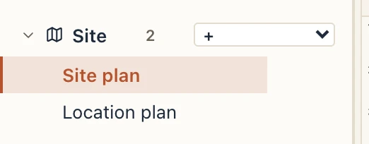
The project browser has a Site under the levels: the site's own drawings, which belong to no storey. A new project starts with two:
- the Site plan (Romanian plan de situație), at 1:500: the whole model seen from above, every storey at once, roofs and all, with the terrain, the paths, the plants, the parcel and the neighbours. What lies wholly under ±0.00 (the foundations) is left out, nothing is cut and nothing hidden is drawn. The parcel's corners are numbered;
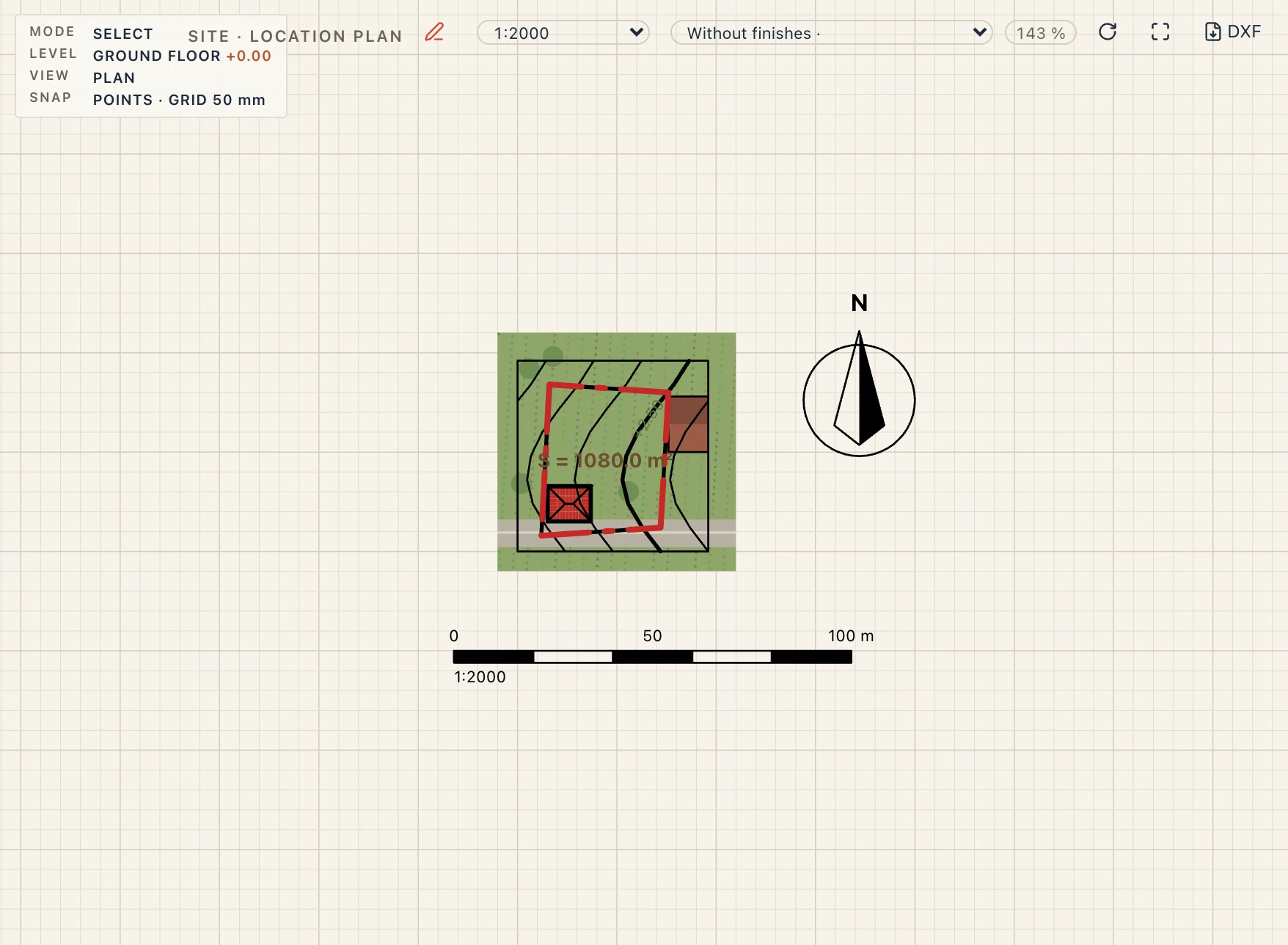
- the Location plan (plan de încadrare în zonă), at 1:2000: the same drawing for the site in its area, over the orthophoto, without the corners' numbers; the project's buildings are filled in red and the parcel is outlined in red, so the site stands out from its neighbours.
+ beside Site makes another of either; the copy buttons duplicate one. Both carry a north arrow pointing to true north (Manage → Location: the angle to true north), a scale bar and, when the project is tied to the map, the coordinate grid: crosses where round eastings and northings meet, every tenth of the scale (50 m at 1:500, 200 m at 1:2000), with their values. Select the view in the browser and set them in its properties, under View settings: what it is (site plan or location plan), the grid's step (0: none), the arrow, the bar, and Highlight the project (the red fill and outline, on by default in a location plan, for a site plan too when you want it).
The map under them. The orthophoto is drawn under every site plan and location plan, whatever storey it was imported on, and prints with them on sheets and in the PDF. For the cadastral plan or the surveyor's drawing, open the site plan and use Import DXF… with Placed: by the map's coordinates. Lapin offers this itself when the file's coordinates look like a map's, for example Stereo 70: the drawing's lower-left corner tens of kilometres from zero, in the file's own unit or in metres. A plan of your own in millimetres is placed by its origin even on a site plan, in the unit the file says. The drawing then lands where its eastings and northings say, through the project's survey point and its angle to true north. If the project is not yet tied to the map, the drawing ties it. Tick As a link to keep it read-only and reload it when the surveyor sends a new one. Import it once into each drawing that needs it.
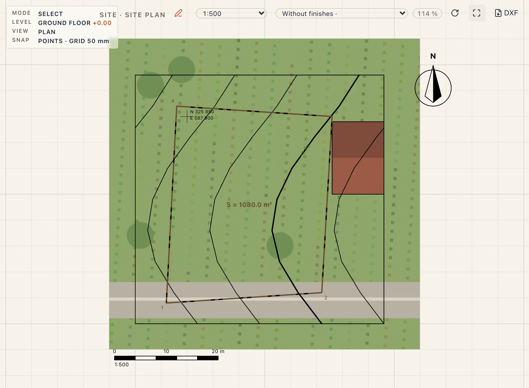
The Parcel coordinates schedule (Schedules → + → Parcel coordinates) is the parcel's coordinate inventory: each corner as the site plan numbers it, its northing and easting in the project's system, the side to the next corner, and the area. Like any schedule it goes on a sheet beside the site plan, and out as CSV or XLSX.
Trees and shrubs
Plant (PN) sets one plant at a click, Planting zone (PZ) sows an outline with a mix of species at a density; select either and choose its species in the properties. The species list is a library of plants native or traditional in Romania, in groups: fruit trees (apple, pear, plum, sweet and sour cherry, apricot, quince), conifers (silver fir, Norway spruce, Scots and black pine), deciduous trees (walnut, lime, birch, maple), shrubs (hazel, cornelian cherry, elder, dog rose, lilac, sea buckthorn, redcurrant, thuja, boxwood) and ground cover. Each comes with its Latin name, its usual height and crown, and is shown by its Romanian name when the interface is in Romanian. The planting schedule lists the Latin and Romanian names beside each species.
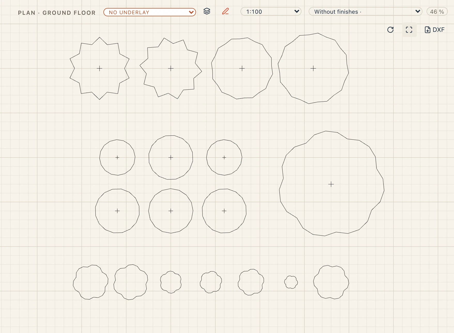
In plan each plant is drawn from above with a thin line, as wide as its crown, by its outline alone: a walnut or a lime a softly lobed crown, a fruit tree a circle, a fir or a spruce a star, a pine a ragged ring, a shrub a small cloud, a clipped hedge plant a circle, with a small cross at a tree's trunk. Elevations and sections draw each plant as one outline: a tree's crown on its trunk, a conifer's cone in tiers, a shrub's dome. A few lines each, so a site plan of hundreds of trees stays light. In 3D conifers are cones, the other trees have a rounded crown on their trunk and shrubs a low dome.
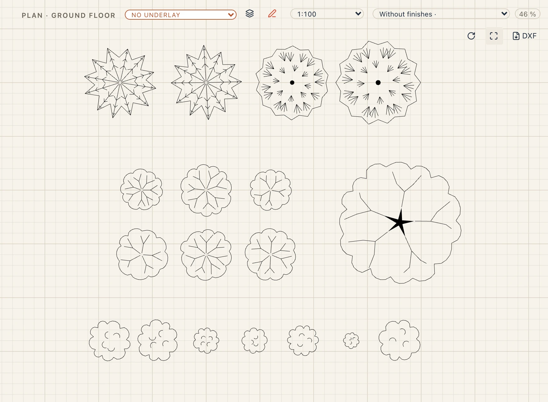
Set the view style's Entourage in 2D to detailed for the landscape drawing's symbols, in black: a fruit tree as a lobed crown with forked branches, a walnut or a lime as a scalloped crown round a dark core, a fir or a spruce as a star of needle sprays, a pine as a round tuft of needles, a shrub as a small cloud. Lapin draws each symbol itself, so neighbouring trees differ a little and a zone never looks stamped; at 1:1000 and smaller (a location plan) only the crowns' outlines are drawn.
People and cars
Entourage (EN) puts a person or a car at a click; choose which in the command line's bar while the tool is on: a man standing, a woman walking, a child, a person on the phone, a car or an SUV / van. Entourage row (ER) puts a row of them along a line you draw: cars every 2.5 m, parked side by side across it with their fronts to its left, people every 1.2 m, walking along it. Each stands on the terrain under it, or on its storey's floor where there is no terrain.
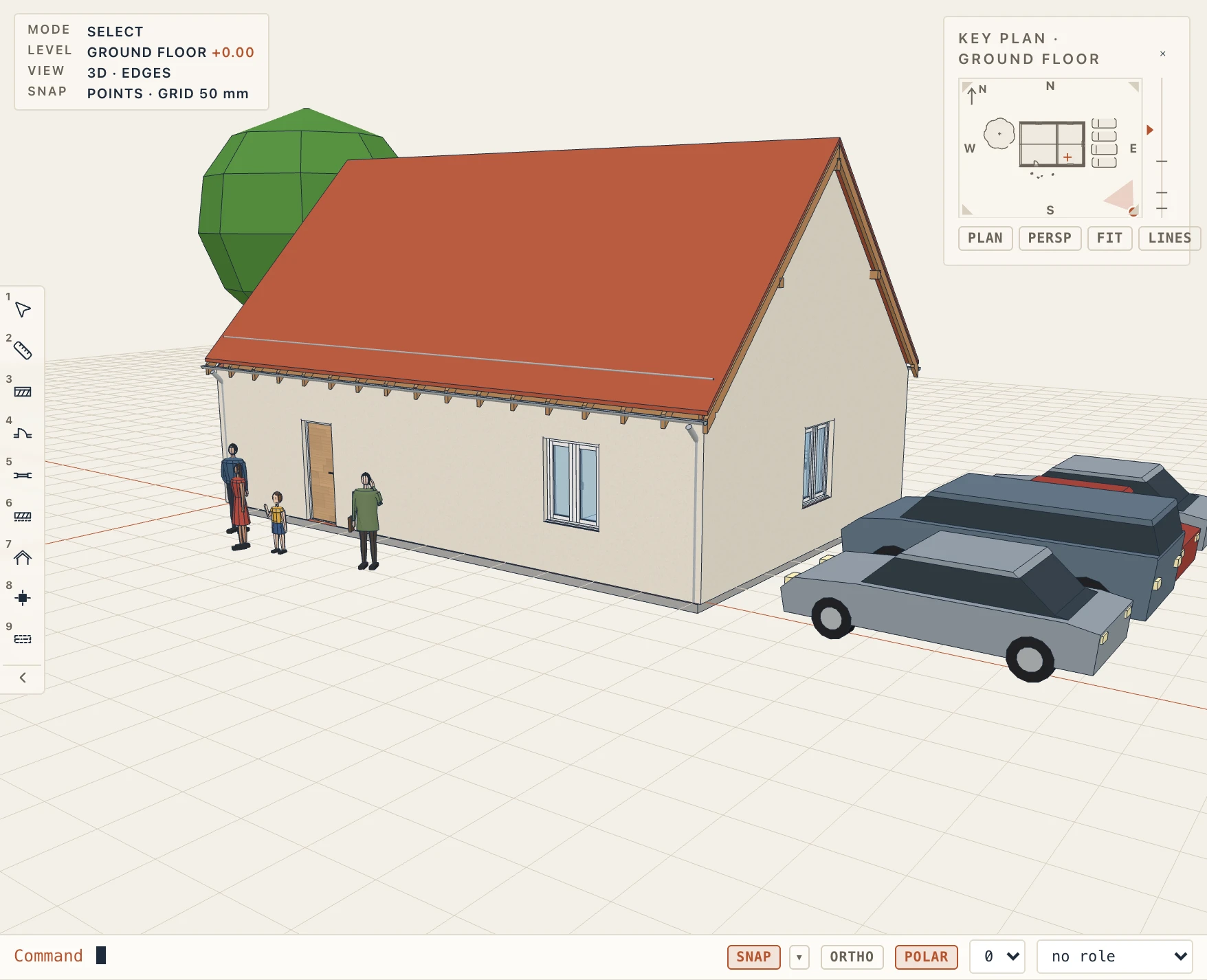
Select one to change it in the properties: its kind, its rotation, its height (its kind's usual size by default), how far above the ground it stands (on a deck or a balcony) and the colour of its clothes or body. Move, rotate, mirror and copy it as any element.
In 3D they are simple figures: people with their limbs, clothes, hair and shoes, cars with their glass, wheels and lights. Drawings keep them simple, as an architect draws entourage, with a thin line: plans and site plans from above, a person's shoulders and head, a car's outline with its corners rounded and its windscreen; elevations and sections as silhouettes, one outline each, a person's figure, a car's side or its front as the view sees it, never the lines of their bodies.
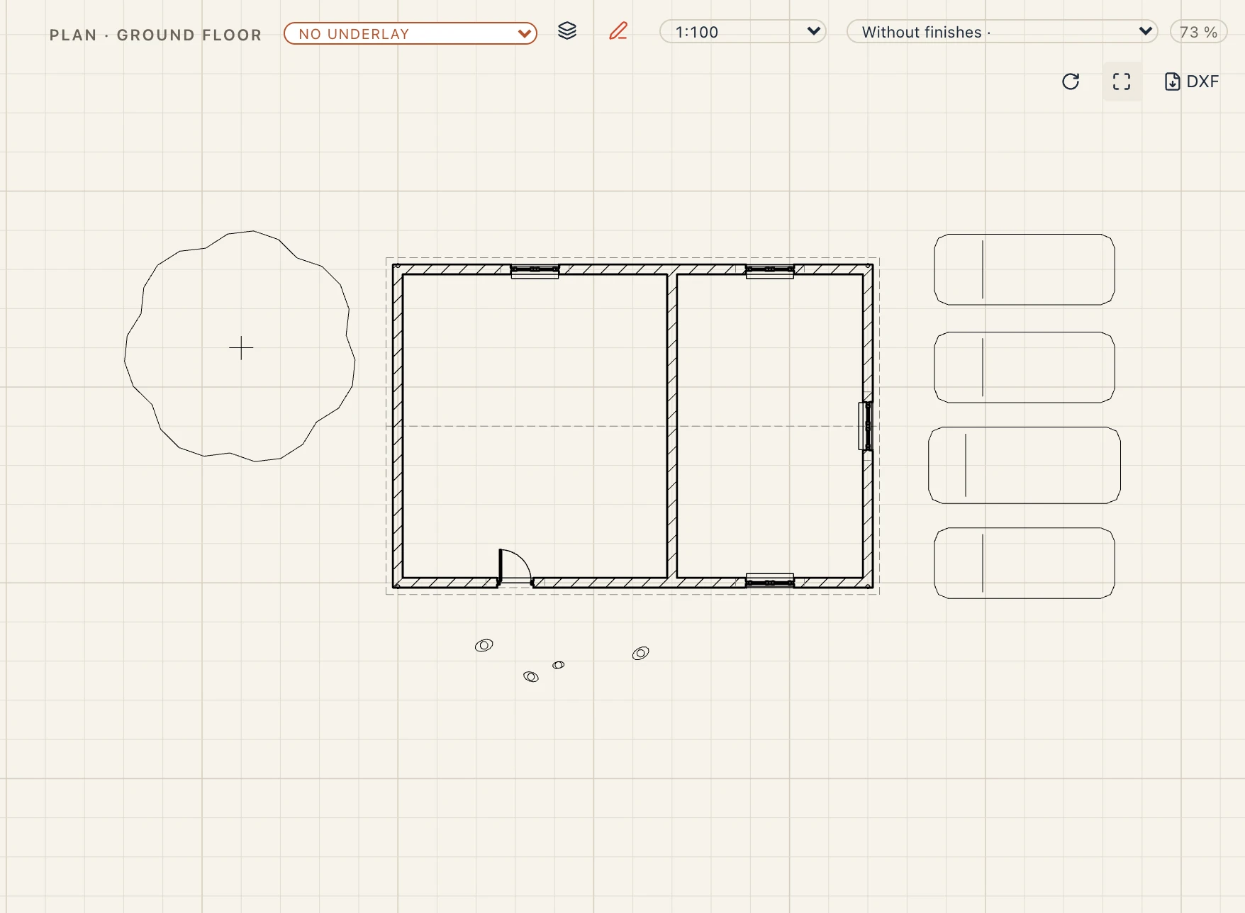
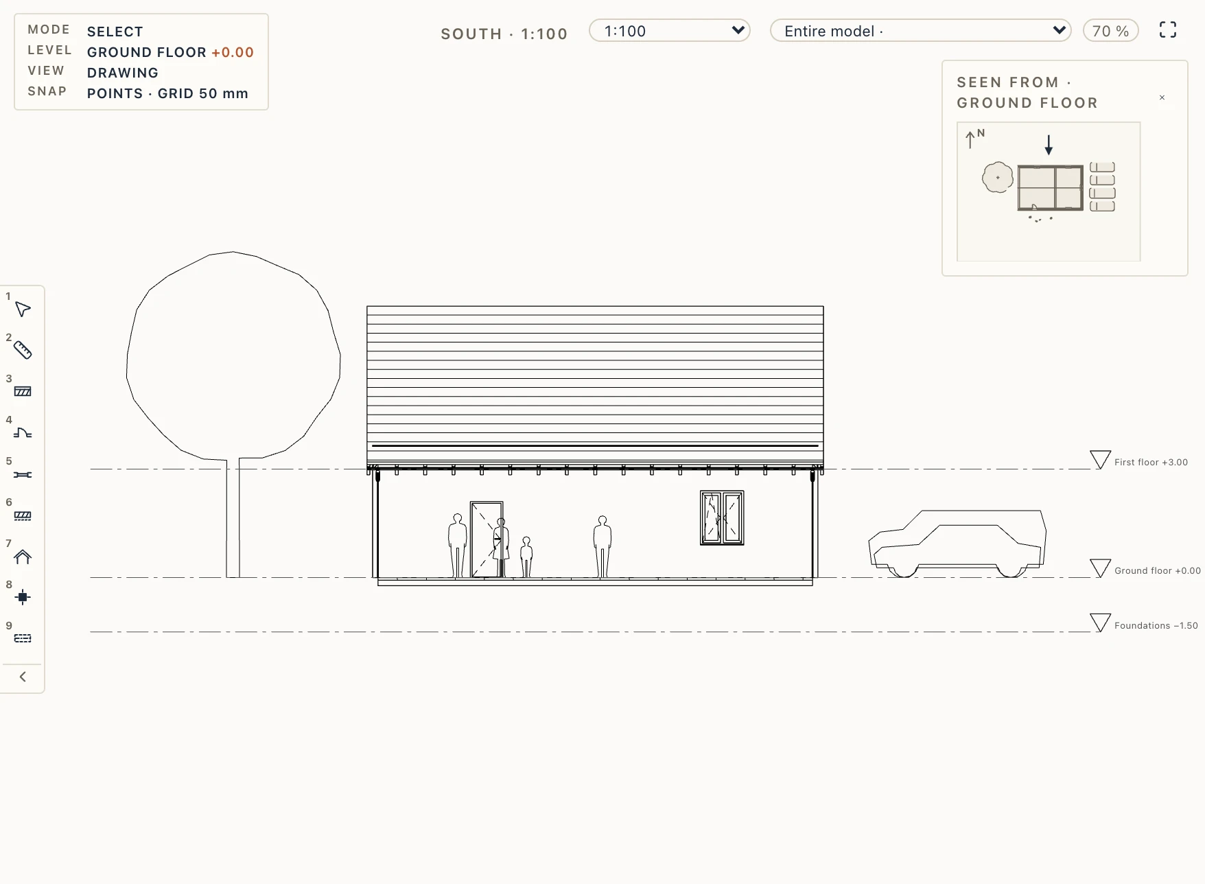
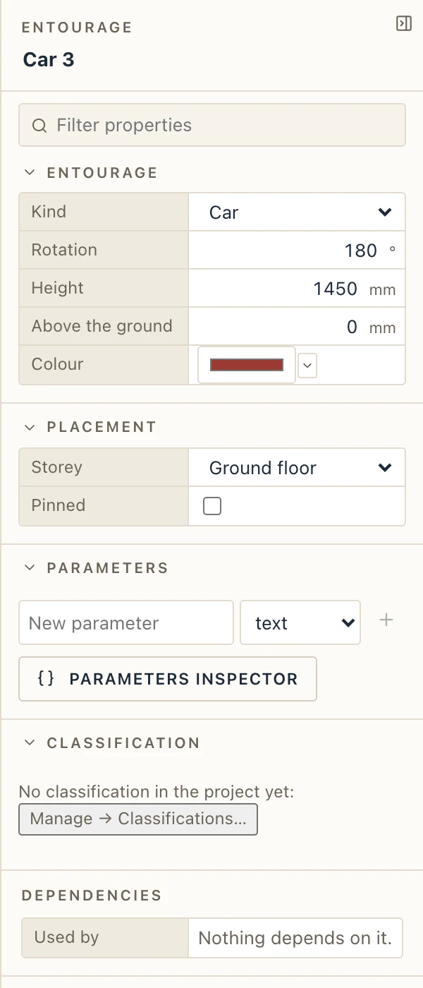
How people, cars and plants draw in 2D is a setting of the view style, Entourage in 2D (in the view's properties or View → View settings; for a whole style, Manage → View styles): outlines (the default), abstract (a person a circle in plan and a head over a body in an elevation, a car a rounded box, a tree a circle with its trunk), detailed (the plants' landscape symbols and every line of the bodies, with the view's sun shadows, as Lapin drew them before) or not drawn. Silhouette fill fills the silhouettes of elevations and sections light grey or pale green. They draw with pen 2 (0.13 mm at 1:100) unless Manage → Object styles gives the Entourage category another, and Visibility / Graphics hides that category in a view. Sheets, the PDF and DXF print them as the view draws them; their 3D bodies never change. Projects made before draw them as outlines too.
They give drawings and pictures their scale but are no part of the building. An IFC or Fragments export (File → Export…) leaves them out unless you tick Entourage in its list of kinds; IFC writes them as IfcBuildingElementProxy "Entourage". The 3D exports (glTF, USD, COLLADA) take them. Clash tests leave them out.
Your own pictures
Entourage kinds… (in the Entourage group) makes kinds of the project's own from pictures: Add picture… takes a PNG or a JPEG (at most 8 MB; one larger than 2048 pixels is scaled down) and makes a kind of it, named after the file, 1.75 m tall and as wide as the picture's proportion says. Change its name, height, width and group in the list (in the project's units): a kind in the Cars group stands in an entourage row every 2.5 m, as cars do. The kinds then appear under Pictures in the command line's bar and in a figure's properties.
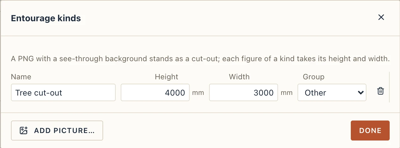
A figure of a picture kind stands as a thin card with the picture on both faces in 3D; a PNG's see-through pixels are cut out, its shadow too, so a cut-out person or tree stands on its own. Drawings show it as the built-in kinds: the card's outline in plan, a flat rectangle as wide and as tall as the picture in elevations and sections, nothing when Entourage in 2D is not drawn. A figure of a picture kind takes its kind's height unless you give it its own; the colour does not apply to it.
The pictures and kinds are kept in the project (saved, undone, versioned) and never written into an IFC; the figures are exported as the other entourage. A kind some figures use is not deleted: Lapin says how many use it, so give them another kind first. A kind deleted takes its picture with it, unless a material or another kind uses it too.
The figures follow the people and cars of BimGo by Aussie BIM Guru (MIT-0): their proportions, stances and profiles.
Gates
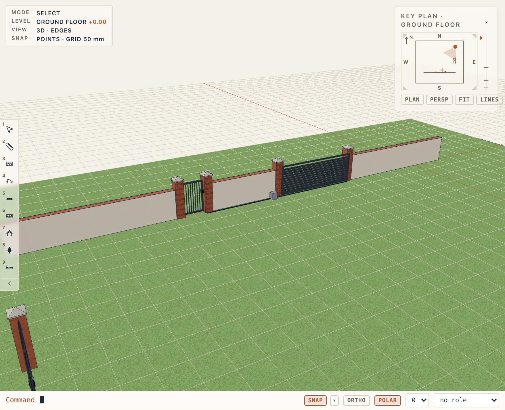
The Gates group on the Site tab places gates with their piers: a Swing gate, a Double swing gate (GT), a Sliding gate, a Cantilever sliding gate, a Pedestrian gate, a Gate with side pedestrian door and a Folding gate. Lapin has no fence of its own: draw the fence as a wall (a low one, of the type you want), or let the gate's piers stand on the parcel's line.
Click the gate's two ends. With On lines on in the bar (the default), the gate's middle goes onto the nearest wall's axis or drawn line within 1.5 m (a wall, the parcel's edge, a drafted line), along it; off, it stands between the two points. The bar also chooses the type it puts down, from the project's styles or Lapin's built-in ones.
A gate set on a wall cuts it from the outer faces of its piers, all the way up, so the fence wall stops at the piers.
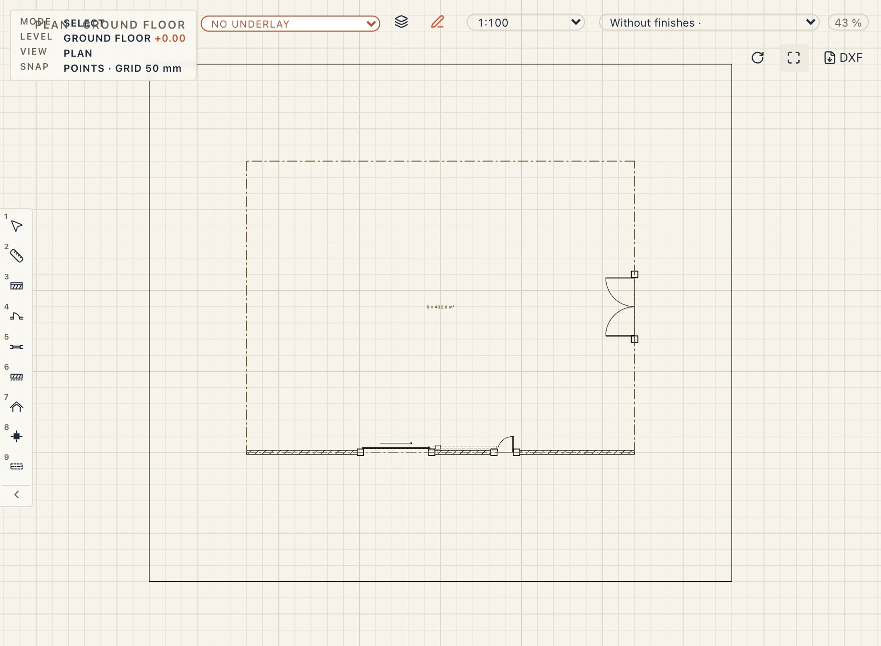
Plans draw the piers as cut, the leaves open by their opening angle with their swing, a folding gate's panels folded; a sliding gate closed, with an arrow the way it opens, its track, and the zone it parks in dashed, as long as its leaf (a cantilever gate's leaf is longer than the opening by its counterweight tail, about 45%). Elevations, sections and 3D draw the bodies.
The configurator
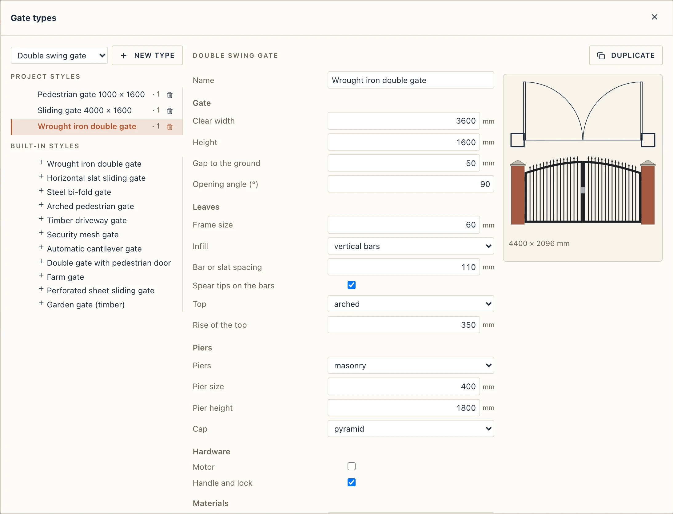
Gate types opens the configurator: the project's styles, and Lapin's built-in ones to add with a click (a wrought iron double gate, a horizontal slat sliding gate, a steel bi-fold gate, an arched pedestrian gate, a timber driveway gate, a security mesh gate, an automatic cantilever gate, a double gate with a pedestrian door, a farm gate, a perforated sheet sliding gate, a timber garden gate). A type sets, by groups, only what its kind takes:
- Gate: the clear width and height, the gap to the ground, a pedestrian door's width, a folding gate's panels on each side, the opening angle;
- Leaves: the frame's size, the infill (vertical bars, horizontal slats, a solid panel, mesh or perforated sheet), the bars' or slats' spacing, spear tips on the bars, the top (flat, arched or pointed) and its rise;
- Piers: masonry, steel posts or none, their size and height, a masonry pier's cap (flat or pyramid);
- Hardware: a motor (an arm on a swing gate's leaves, a box beside a sliding gate's track) and a handle and lock;
- Materials by role: frame, infill, piers, caps, hardware and motor. A material named here that the project has not is made.
The preview is the engine's: the plan with its swing or its parking zone above, the elevation below. Every gate of a type follows a change.
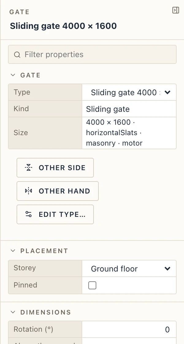
Select a gate to change its type, its turn, how far above the ground it stands, which side its leaves open to, on which hand its hinges are (or a sliding gate parks), and how far it is drawn open (0: closed). Other side and Other hand in its properties, or the arrows by it in plan, flip them. Modify → Mirror gives it its other hand.
Schedule, cost and IFC
The Gate schedule lists the gates by type: kind, clear size, leaves, infill, top, piers, motor and how many. A new type has the cost articles LAP-GATE and, with a motor, LAP-GATEMOT, counted per gate.
IFC writes a gate as an IfcDoor of PredefinedType GATE, of an IfcDoorType with its operation (DOUBLE_DOOR_SINGLE_SWING, SLIDING_TO_LEFT, DOUBLE_DOOR_FOLDING…; a gate with a pedestrian door USERDEFINED), its clear width and height as OverallWidth and OverallHeight and Pset_DoorCommon. The piers are part of the gate's body, so one element carries the gate as it was configured, and Lapin reads it back as its own gate.
Planning rules and the sun (Lapin Urban)
The Lapin Urban edition adds a Planning group to this tab: the parcel's planning rules (POT, CUT, the maximum heights, the setbacks from the street, the sides, the rear and the road's axis), the buildable volume they leave, the indicators the model reaches against them, and the sun study: the sun and its shadows in 3D for any day and hour at the project's place, and shadow plans for the equinox and the solstices.