User guide
Sections, elevations and 3D
Make sections and elevations, open 3D views, and set what each view shows and how.
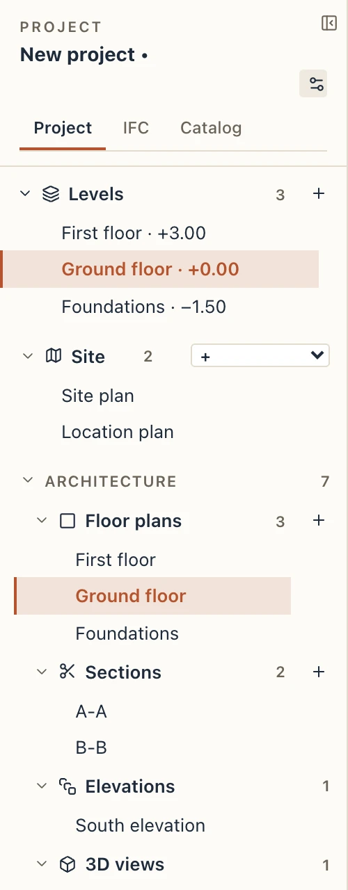
All the views are in the project browser, filed under their discipline: Architecture, Structure or MEP. Double-click a view to open it in a tab.
Sections
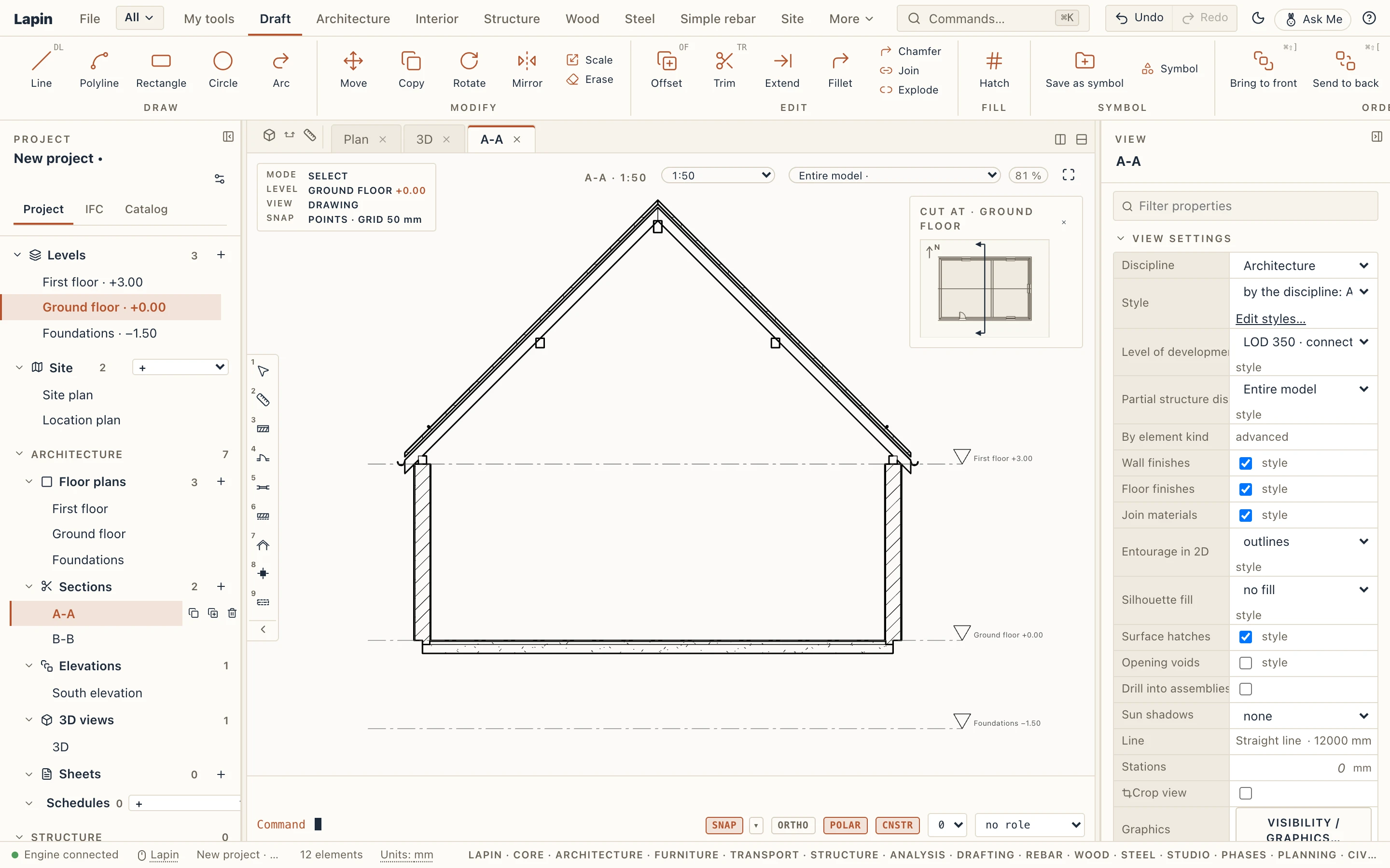
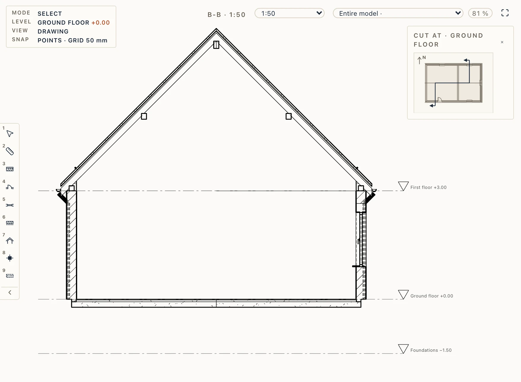
Choose View → Section (SE), or click + next to Sections in the browser. Then draw the cut line in a plan with two clicks, and click a third time on the side the section looks to. The section is drawn from the model and stays up to date as you change it.
A section need not be one straight line. Jogged section (SJ) draws it as a polyline, click after click, and Enter finishes. It is drawn projected by default, as in Revit: the pieces parallel to the first one cut the model, each seeing only its own stretch, the jogs between them cut nothing and add no width, and everything is drawn in one frame along the first piece, so a grid line or a column stands in the section exactly where it crosses in plan. A piece within 1° of the first counts as parallel; any other piece is a jog, and where it runs at an angle the cut moves from one parallel piece to the next at its middle. Set Jogged to Developed in the view's settings to cut along every piece instead, the jogs too, each seeing only between its own ends, drawn side by side at their real lengths with a fine dashed line marking each jog (a line that turns back over itself is always drawn developed). Curved section (SV) draws an arc through three points (its start, its end, a point on it) and unrolls it the same way, so a curved facade reads at its true length. Section along (SA) picks an element with a line in plan, a road or a path, a ditch, a retaining wall, a wall, a beam, a footing or a drafted polyline, and follows it as it is now; it writes the stations along the bottom (0+020, every tenth of the scale, or the step you set under Stations in the view's settings). In the plan, a section's points are grips: drag one, drag a piece's middle to add a jog, Ctrl/⌘-click a point to take it out. Shown in 3D, a jogged or developed section cuts the model along its first piece and lays its drawing piece by piece, each on its own plane.
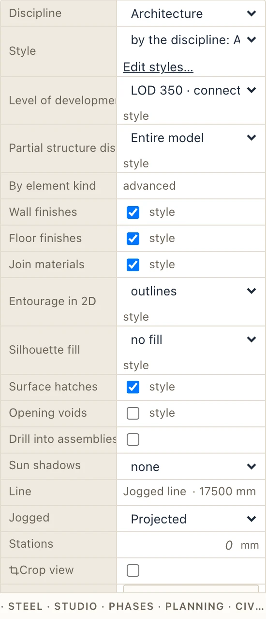
Select the section in the browser to set its scale, its depth, its discipline and its style in the properties panel.
The view's scale. At the top of a plan, a section or an elevation, beside the zoom (its size on screen against paper), the scale picker shows the view's scale and changes it: one of the project's standard scales, or Custom… for one of your own (1:75), in one step to undo. On a sheet, pick a view and its scale shows there too; changing it changes the view, on every sheet that shows it. Default scales… opens Manage → Drafting standards → Project: Standard scales are the scales the picker offers, and New plans at 1:, New sections at 1: and New elevations at 1: the scale each new view takes (empty: 1:100). A level's plan with no view of its own draws at the plan scale.

Where a section is marked
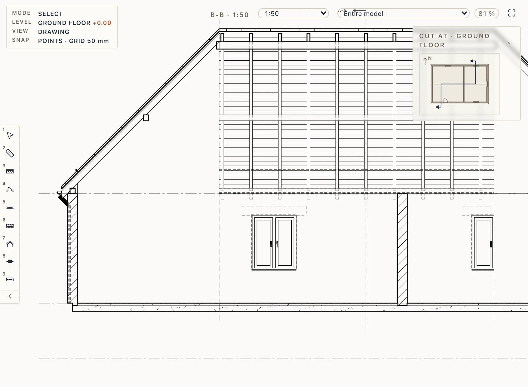
A section's line is drawn in every plan, and the section is marked in every other section and elevation its plane crosses: a fine dashed line where the plane cuts the view, with the section's name and an arrow looking the way the section looks at its top, the same size on paper as in a plan. A section is never marked in itself. Click a marker to select the section, double-click it to open it.
Marker size. Manage → Drafting standards → Project sets how large the markers are drawn, in paper millimetres, for sections and elevations apart: Section marker size (a section's arrows are 0.7 of it) and Section marker text, Elevation marker size (the elevation's circle across) and Elevation marker text; 10 mm and the Standard text style's height until you set them. A project that had one marker size keeps it for both. A section or an elevation of its own size has Marker size (mm) and Marker text (mm) in its properties; empty, it takes the project's. The engine draws the markers, so plans, the sections they cross, sheets, the PDF and the DXF all follow.
Moving a section. Select the section in a plan and move it with Move (or drag it by its line): as in Revit, it cuts where you put it, and turned or mirrored it looks the turned or mirrored way. Each head (its arrow and name) has a grip of its own: drag it to move the head off the line's end, for example clear of a dimension, and a fine leader joins it back; the section cuts the same. Ctrl/⌘-click the grip to put the head back. A section across or along an element follows the element and is moved with it.
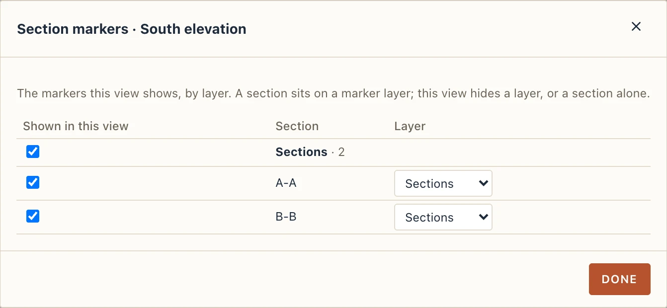
Each section sits on a marker layer (Sections at first; Marker layer in the section's properties changes it), and each view chooses what it marks. View → Sections… lists the project's sections by layer for the view in front, with a checkbox per layer and per section for this view alone, the layer of each section (an existing one, or New layer…), and in how many views each is hidden. A sheet marks what its views mark.
A section cut across a beam or a column (Section here, Section across on the Simple rebar tab) has grips in plan too: drag either end along the line to give that side more or less margin, drag the middle along the element to move the station it cuts at. The section's window follows.
Elevations
+ next to Elevations makes the four elevations of the building at once.
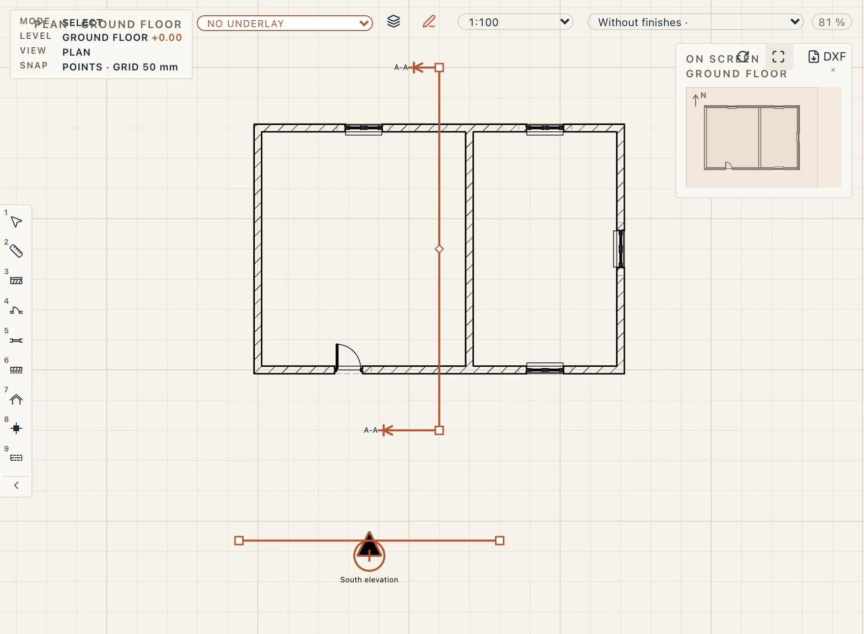
Every plan marks each elevation in front of the building, clear of the sections' heads there: a fine chain line across the way it looks, and in its middle a circle whose black arrow points at the building, with the elevation's name behind it. Click the marker to select the elevation, double-click it to open it. Elevation marks in Visibility / Graphics (VV) hides them in a view.
How far an elevation reaches. Select the elevation in a plan: its line has a grip at each end. Drag one along the line to stretch or shorten the elevation on that side; the elevation then draws only what lies between the two ends, and its sheets and PDF follow. Each drag is one undo step. Until you drag them, the line spans the whole building and grows with it.
Moving an elevation's marker. Drag the circle's grip, or select the elevation and use Move: the marker goes where you put it, further out from the building or along its line, in one undo step. As in Revit, the marker's line is where the elevation starts seeing. Left outside the building, where a new elevation's marker stands, it sees the whole building. Moved into the building, it shows only what lies beyond its line, and what the line cuts is drawn cut, with the materials' cut hatches, as in a section: an interior elevation. Its reach along the line keeps its own grips. An elevation looks north, south, east or west, so it is not turned or mirrored. A pinned elevation or section (Modify → Pin) is not moved until it is unpinned.
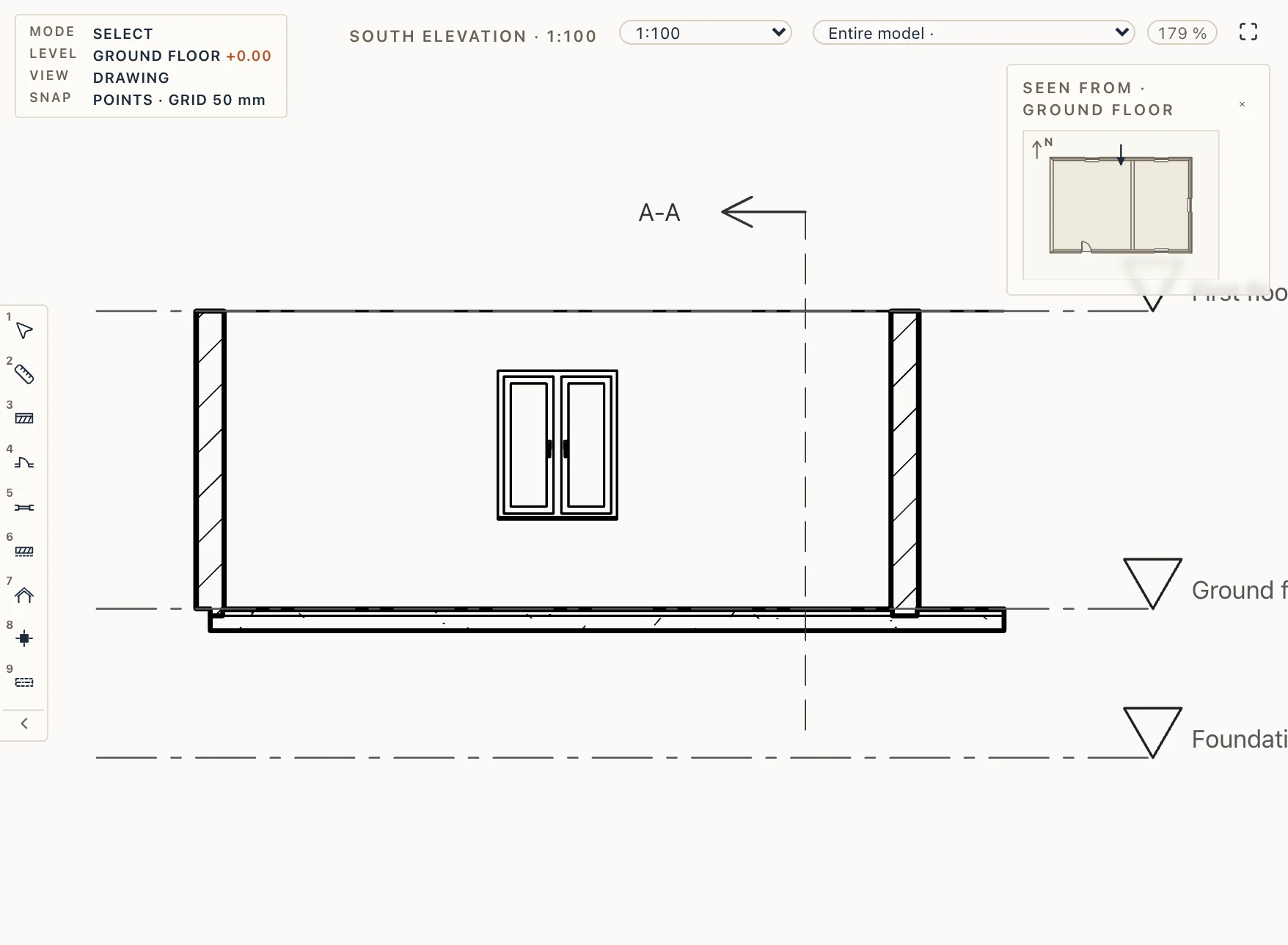
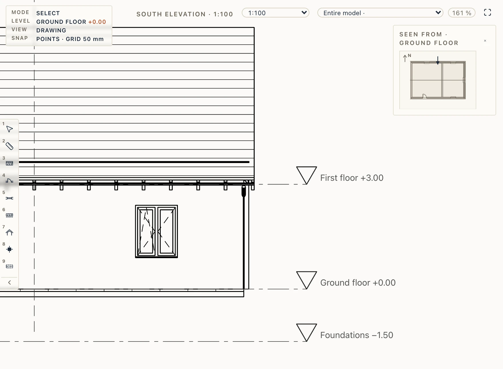
Sun shadows
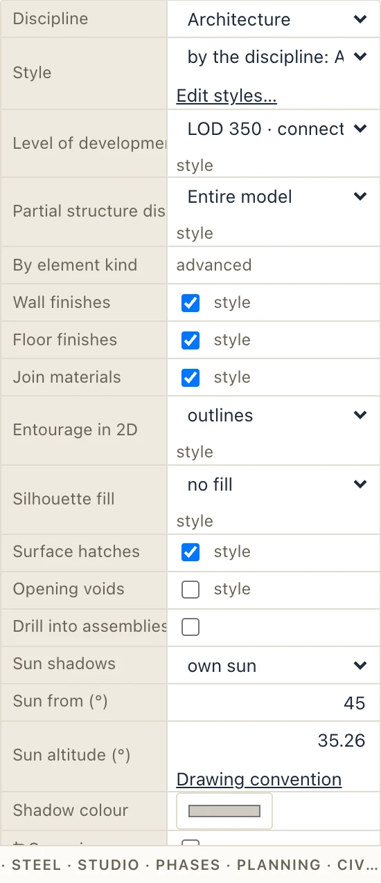
An elevation, a section or a site plan can draw the shadows the sun casts on what it sees, filled under its lines, so they print on sheets and in PDF and DXF. Choose them in the view's properties, under Sun shadows:
- own sun: a sun of the view's own. By default the drawing convention: the sun over your left shoulder, its rays along a cube's diagonal (from 45°, 35.26° high), so a shadow is as deep as what casts it stands out. Sun from and Sun altitude turn it; Drawing convention brings it back.
- project sun: the sun of the project's place (Manage → Location) on a day and at an hour of the view's own. As in Sun and shadows takes the day and hour of View → Sun and shadows.
A section casts and receives only what lies beyond its cut. A storey plan draws no shadows: its walls, cut at the plan's height, would cast them too short.
Surface hatches
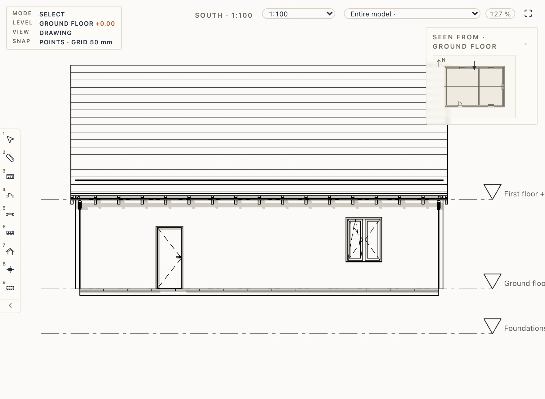
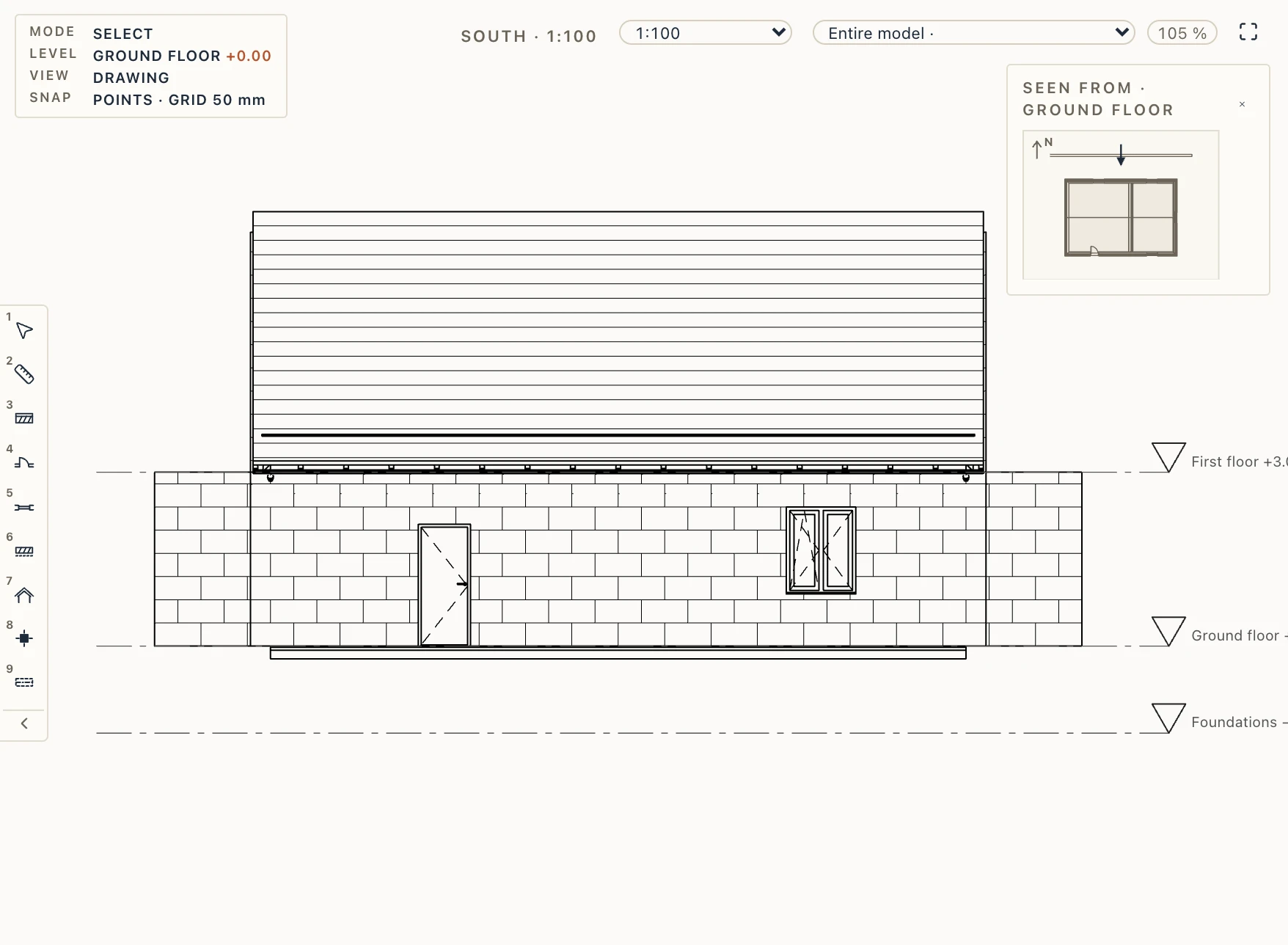
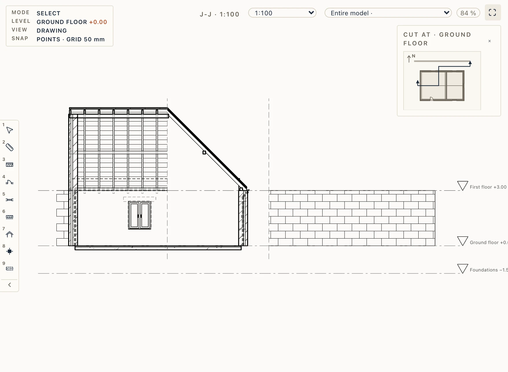
An elevation or a section hatches each face it sees with its material's Elevation hatch (Manage → Materials, the 2D graphics tab): its pattern, scale, angle, pen and fill. Only the part of a face no nearer element hides is hatched, so a facade's render or brick shows round its doors and windows, and a section hatches what it sees beyond its cut, not behind the elements it cuts. A layered wall shows its outermost layer's material. The hatch is drawn under the lines, so it prints on sheets and in PDF and DXF (layers SURFACE-HATCH and SURFACE-FILL).
With Alignment view the pattern runs on from one face to the next; with layer it lies on the face itself, along its level line from its bottom corner, and a face seen at a slant shows it foreshortened. One material going on in one plane across several elements is hatched as one, unless the view style's Join materials is off.
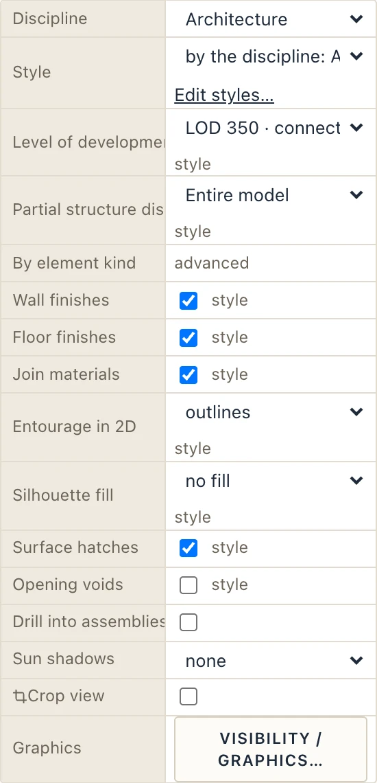
Until you choose one, a material's elevation hatch comes from the name, as its section hatch does, and Manage → Materials shows which (from the name (BRICK)): brick and masonry BRICK, stone STONE, timber BOARDS, metal cladding VERTICAL, roof tiles, shingles and slates HORIZONTAL, tiles TILES, gravel and earth as in sections. Insulation, membranes, plaster, render, paint and concrete get none: insulation's BATT is a section's hatch, never suggested for a surface (chosen by hand, it is drawn). Choose none to draw nothing. A jogged, curved or along-an-element section hatches each of its pieces between the piece's ends, and draws their sun shadows the same way. The view style's Surface hatches (View → View settings, Manage → View styles) turns them off for whole views: on in Architectural, off in Structural, MEP and Coordination. Plans keep their own cut and plan hatches. A roof's covering is hatched by its covering material, so a tiled roof shows its courses on the slopes the view sees, and none on those turned away.
3D views
Double-click 3D to open the 3D view. Drag with the left button to orbit around the model. The key plan at the top right shows where you are looking from. Plan, Persp and Fit change the camera. To keep a camera, duplicate the 3D view.
The mouse wheel zooms to the point of the model under the cursor, which stays where it is on the screen; the zoom stops just short of that point and never passes through it. A drag with the left button turns the view round the selected elements' middle, which stays where it is on the screen, so you can look at them from every side; with nothing selected it turns round the point of the model under the cursor where the drag starts, and round the middle of the view if the cursor is over empty space. View → Zoom to cursor and View → Orbit around selection turn each off (the wheel then zooms to the middle of the view, and the view turns round its middle), and so do the checkboxes in a 3D view's properties. The choice is kept on this computer.
X-ray, or a see-through view
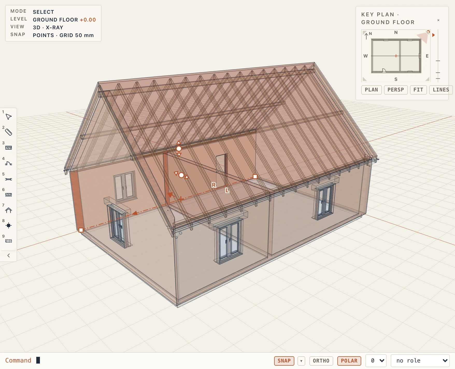
View → Visual style goes round shaded, shaded with edges, X-ray and wireframe; View → X-ray switches X-ray on and off directly. In X-ray every surface of the model is drawn see-through, its edges kept, so you can see through walls and floors to what is behind them. What is selected stays solid and highlighted, and a click still picks the element under the cursor. The style is the 3D view's, for looking only: it changes nothing in the model, the drawings or the exports. To make only some categories see-through (the roof, the slabs, the walls), set their transparency per category in Visibility / Graphics (VV); that one also reaches sheets and exports.
A section in 3D
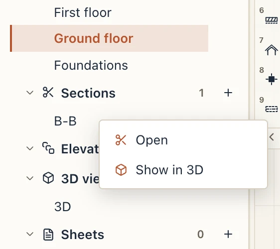
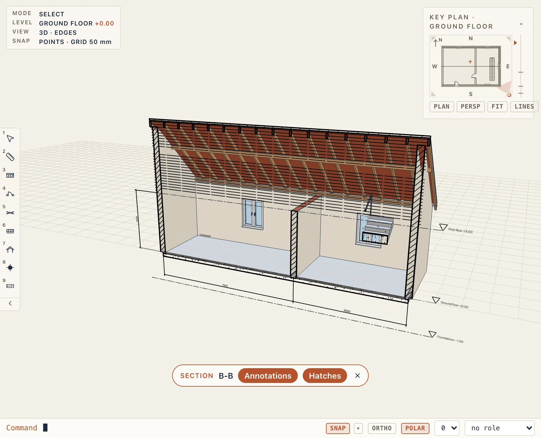
Right-click a section in the browser and choose Show in 3D. The 3D view cuts the model along the section's line. It keeps the side the section looks at, up to the section's depth if it has one. Every cut element is closed where it is cut, layer by layer, each layer in its own material: a wall shows its brick core and its plaster, as solid as the wall is. Hatches on the chip at the bottom of the 3D view lays the section's drawing on the cut instead, with the cut fills and hatches a sheet prints. The section's dimensions, level marks, tags and texts lie on the same plane, the same size and in the same place as in the section. Lines keep their pen weights and their full dash patterns. Those drawn beside the building stand in the air beside the cut. Annotations on the chip at the bottom of the 3D view hides them or shows them again. An elevation's Show in 3D turns the camera to look the way the elevation does.
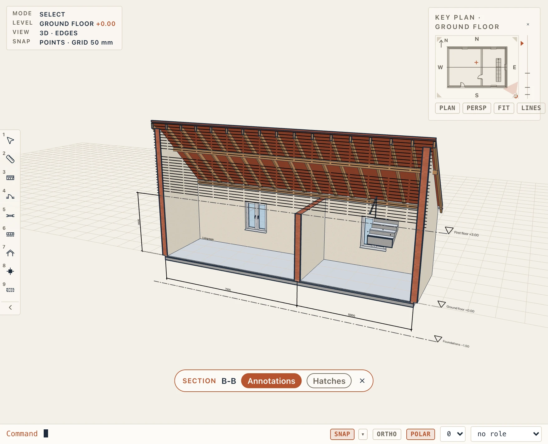
To see the whole model again, click the × on the Section chip at the bottom of the 3D view, or choose Show in 3D again.
The section box
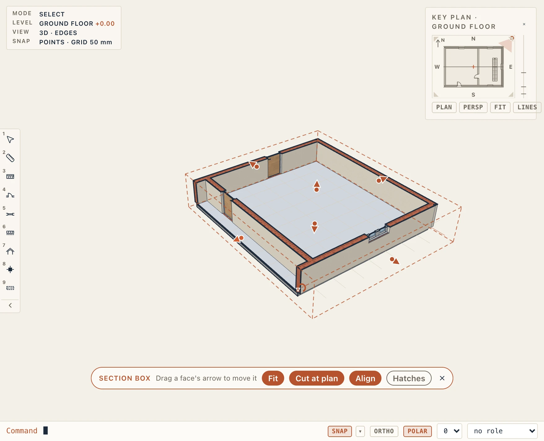
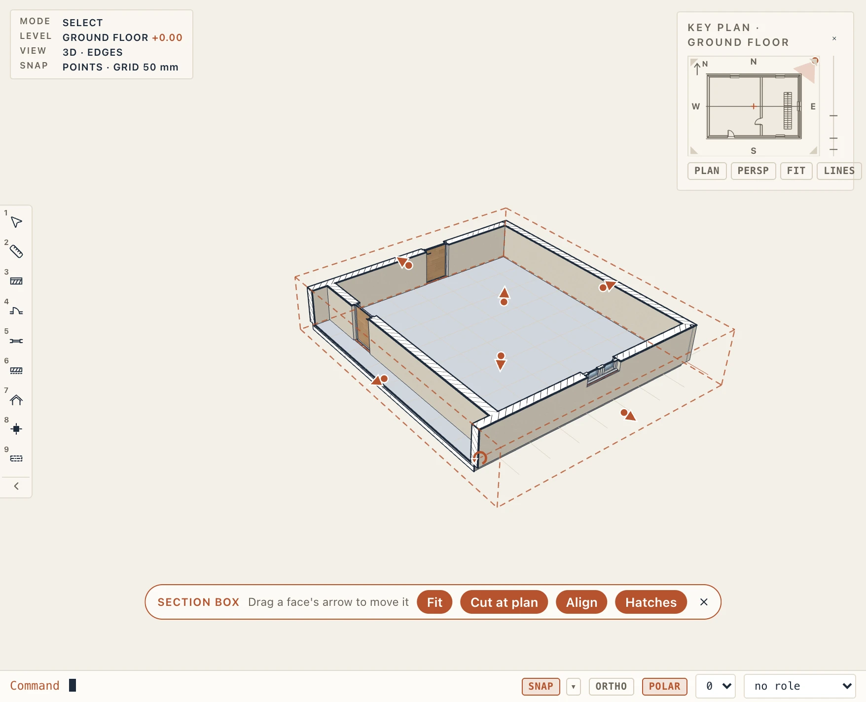
View → Section box (shortcut BX) cuts the 3D view to a box. The box starts round the whole model. Each face has an arrow in its middle: drag it to move that face. Every element the box cuts is closed on that face, layer by layer, in its materials, and the faces meet cleanly at the box's edges. Cut at plan sets the box's top at the active level's plan cut (its view range), so the level reads in 3D as its plan cuts it. Fit puts the box back round the whole model. To turn the box, drag the round handle past its top corner (by the degree; hold Shift for 15° steps), or select a wall and click Align: the box turns the way the wall runs. Hatches draws the box's cuts as a sheet does, each material with its cut fill and hatch, instead of the materials. A saved 3D view keeps its section box: save the view with the box on, or open a saved view and set its box, and the box is there each time the view opens. Hide box on the Section box chip hides the box's frame and handles so they do not stand in the picture, while the cut stays active; Show box brings them back (the choice is not saved with a view). The × on the chip turns the box off.
One storey at a time
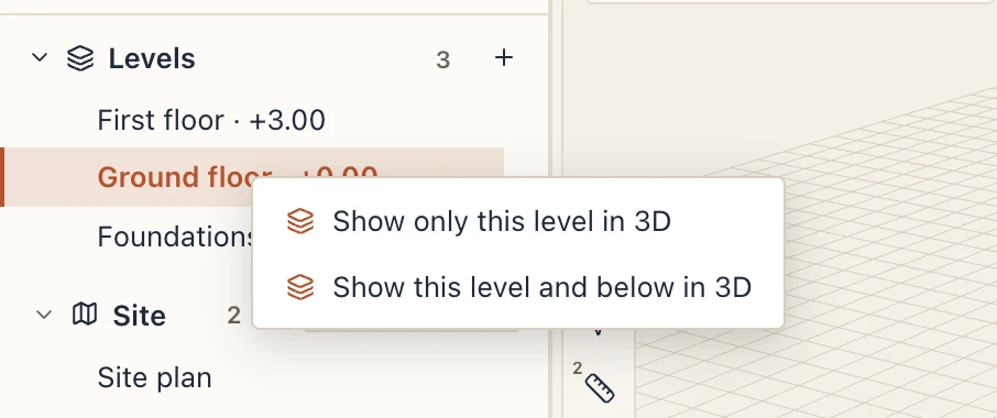
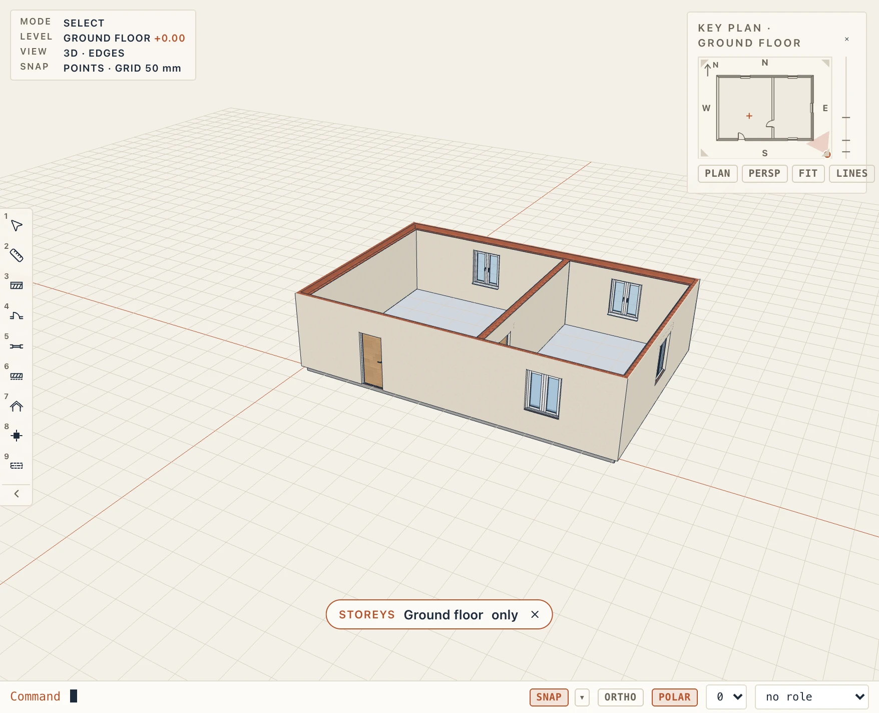
To look inside the building, show only some of its storeys. Right-click a level in the project browser and choose Show only this level in 3D, or Show this level and below in 3D to see the building cut at that level. The level becomes the active one, and the 3D view follows the active level: click another level in the browser to go up or down a floor.
View → Storeys shown, or the 3D view's properties, sets the rest:
- Show: every storey, the storeys ticked, the active storey only, or the active storey and those below.
- On no storey: what stands on no storey (the site, the terrain, linked files) is shown or hidden.
- Cut above its level: the model is cut that far above the highest storey shown, 1.20 m at first, as a plan cuts it. Every element cut there is closed on the cut, layer by layer, in its materials, as a section shown in 3D is.
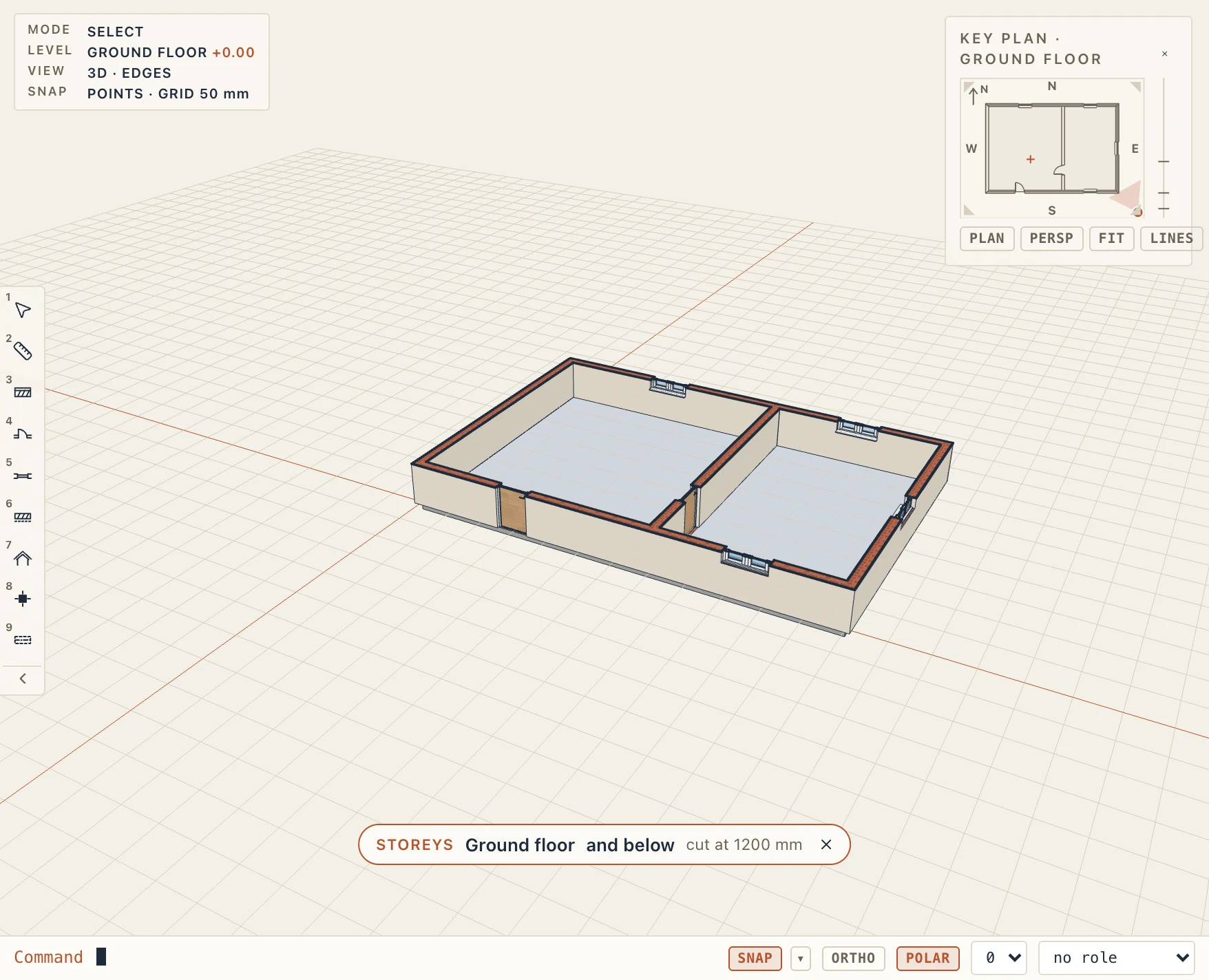
The storeys hidden are not drawn, and you cannot select them, fit to them or walk on them. What a cut takes away (the cut above the storeys shown, a section shown in 3D, the section box) is not there for a walk either: you walk past a wall's upper part the cut has removed, and the caps on the cut close what it opens. File → Export 3D… takes the 3D view as it shows it (see Import and export). A saved 3D view keeps its own choice. The Storeys chip at the bottom of the 3D view says what is shown; its × shows every storey again.
Without finishes, or the cores only
A 3D view can show the structure of the building alone, as a structural plan does. In the 3D view's properties (with nothing selected), or in View → View settings with the 3D view in front, Partial structure display shows:
- Entire model: the walls, floors and footings as they are built;
- Without finishes: without the layers whose material is a finish (plaster, render, paint, tiles, boards, floor coverings, or a material whose category is Finish in Manage → Materials); the insulation stays;
- Core only: only the layer marked as the core (the brick, the concrete slab);
- Core of load-bearing elements only: the cores of the load-bearing elements alone (see Partial structure display).
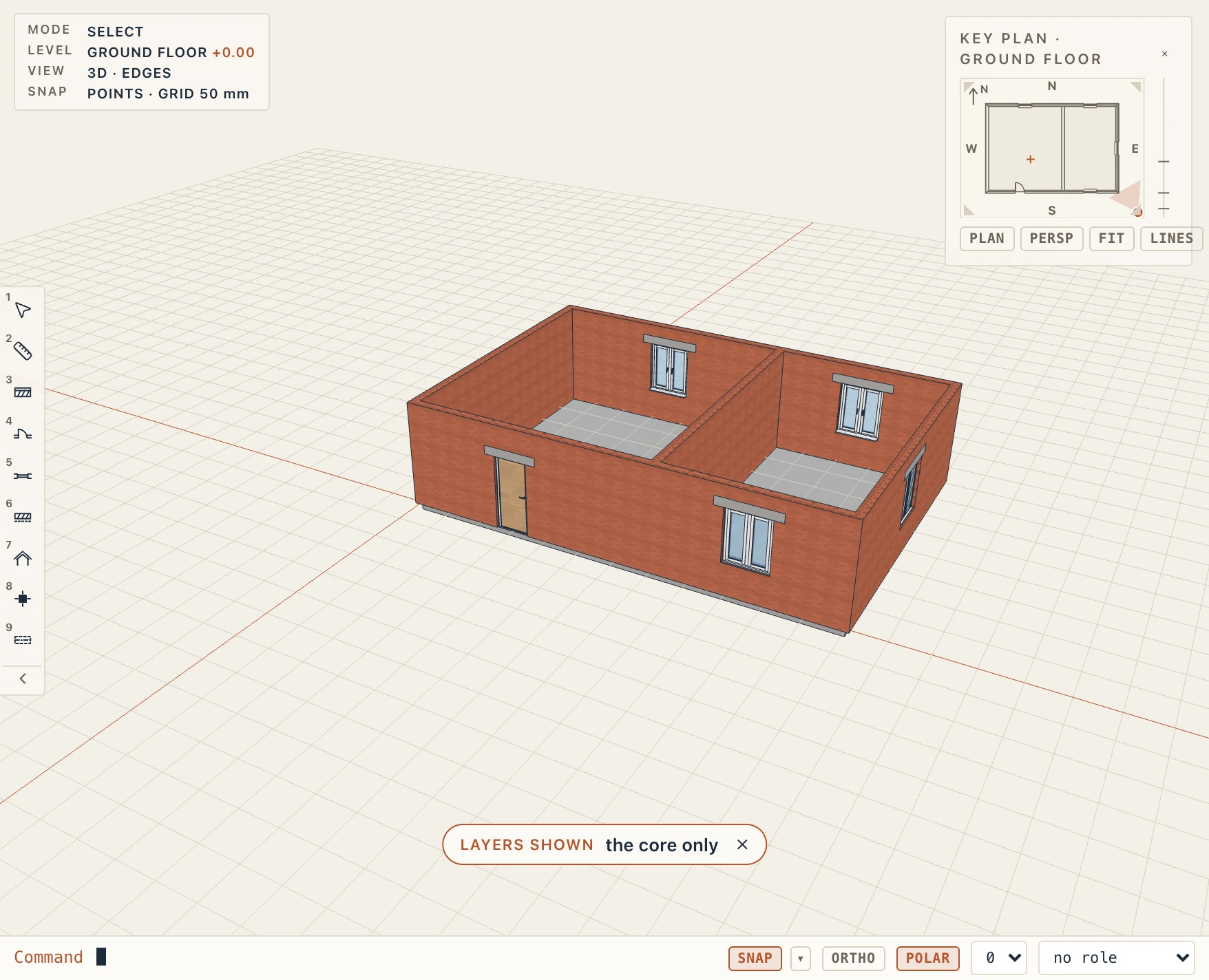
Each layer kept stays a closed solid in its own material, so a cut or the section box closes it as before. Doors and windows stay in their openings; a reveal lined in a finish goes with the wall's finishes. A 3D view takes its layers from its style, like a plan: set its Discipline to Structure and it shows the cores only; set Partial structure display to choose otherwise, and the button beside it goes back to the style's. The Layers shown chip at the bottom of the 3D view says what is left out; its × shows every layer again. The layers hidden are not selected or walked against, and File → Export 3D… as the view shows it exports the same layers.
Walking into a room
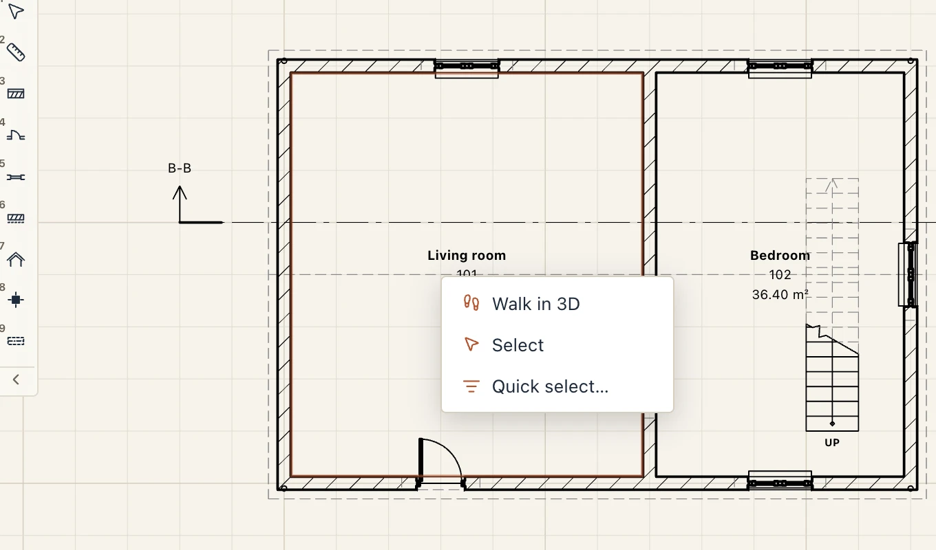
In a plan, right-click inside a room and choose Walk in 3D. The 3D view puts you inside the room, 1.60 m above its floor, looking along its longest side.
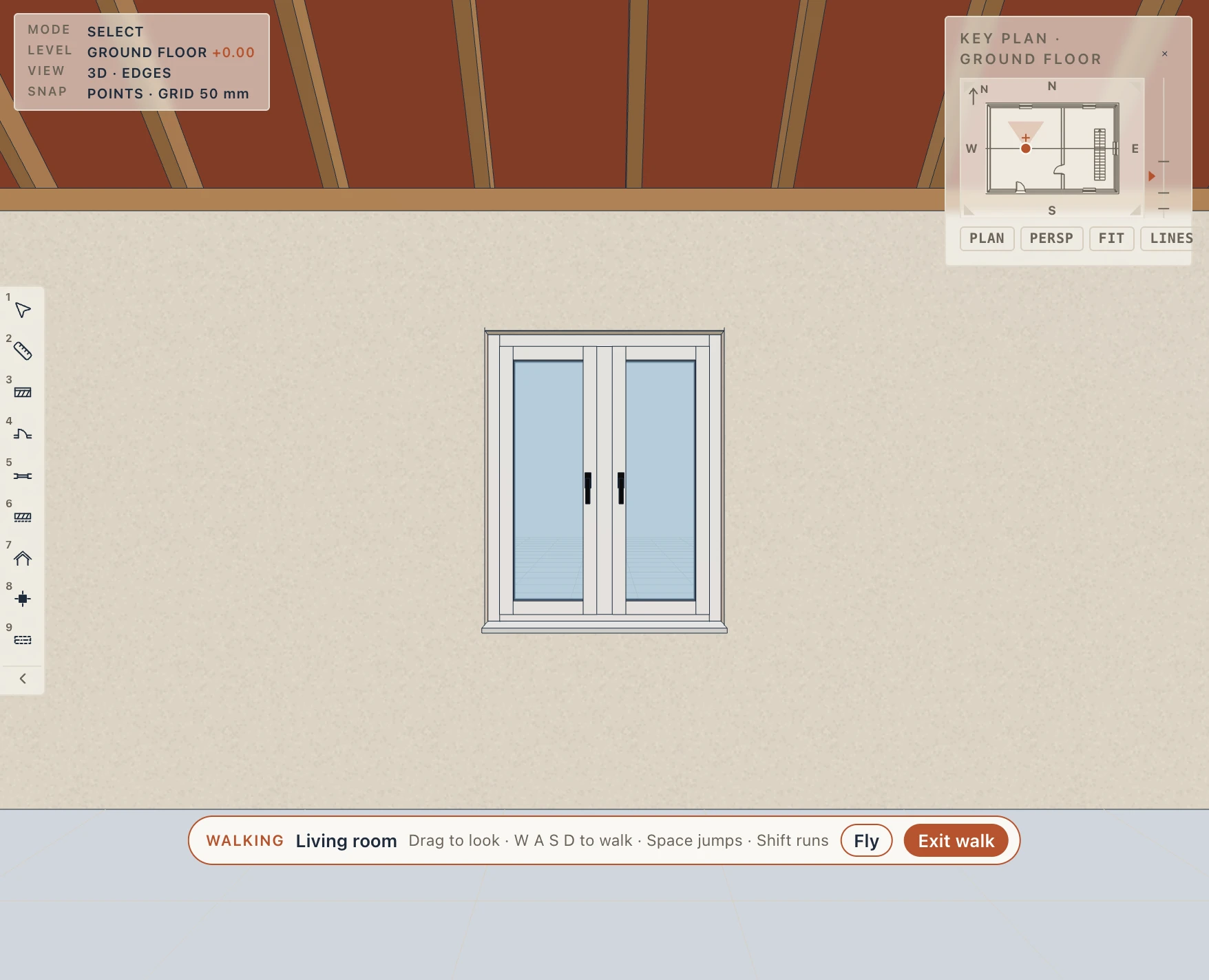
- Drag with the left button to look around.
- W A S D or the arrow keys walk. Hold Shift to run. Space jumps.
- The mouse wheel steps forward and back.
You walk as a person would. Walls, columns, furniture and closed windows stop you, and you slide along them. You stand on floors, walk up and down stairs and ramps, and fall if you walk off an edge. Doors are open for you: walk through their openings. Only what the 3D view draws stops you: hidden elements, the storeys it does not show and what its cuts take away are not in your way.
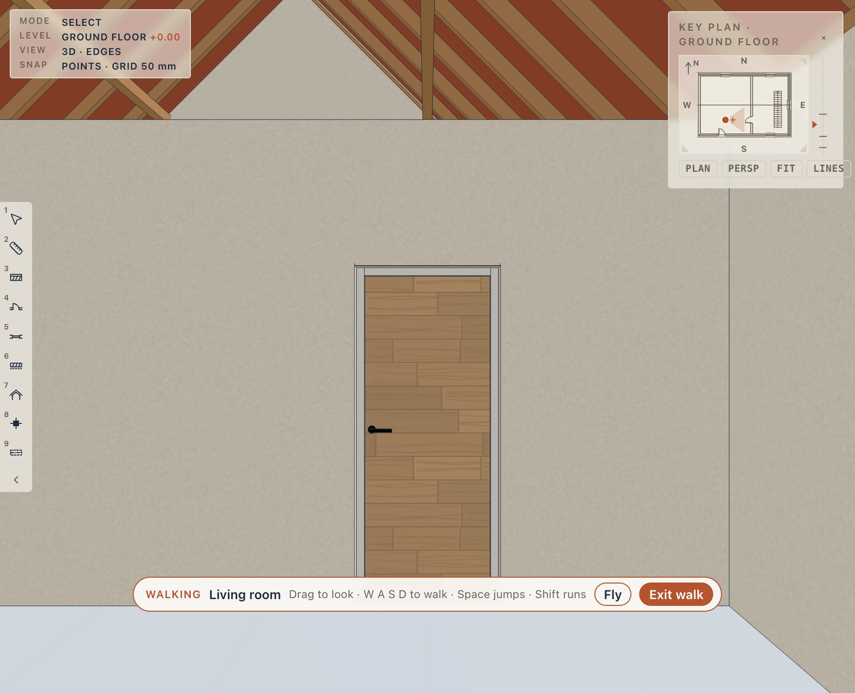
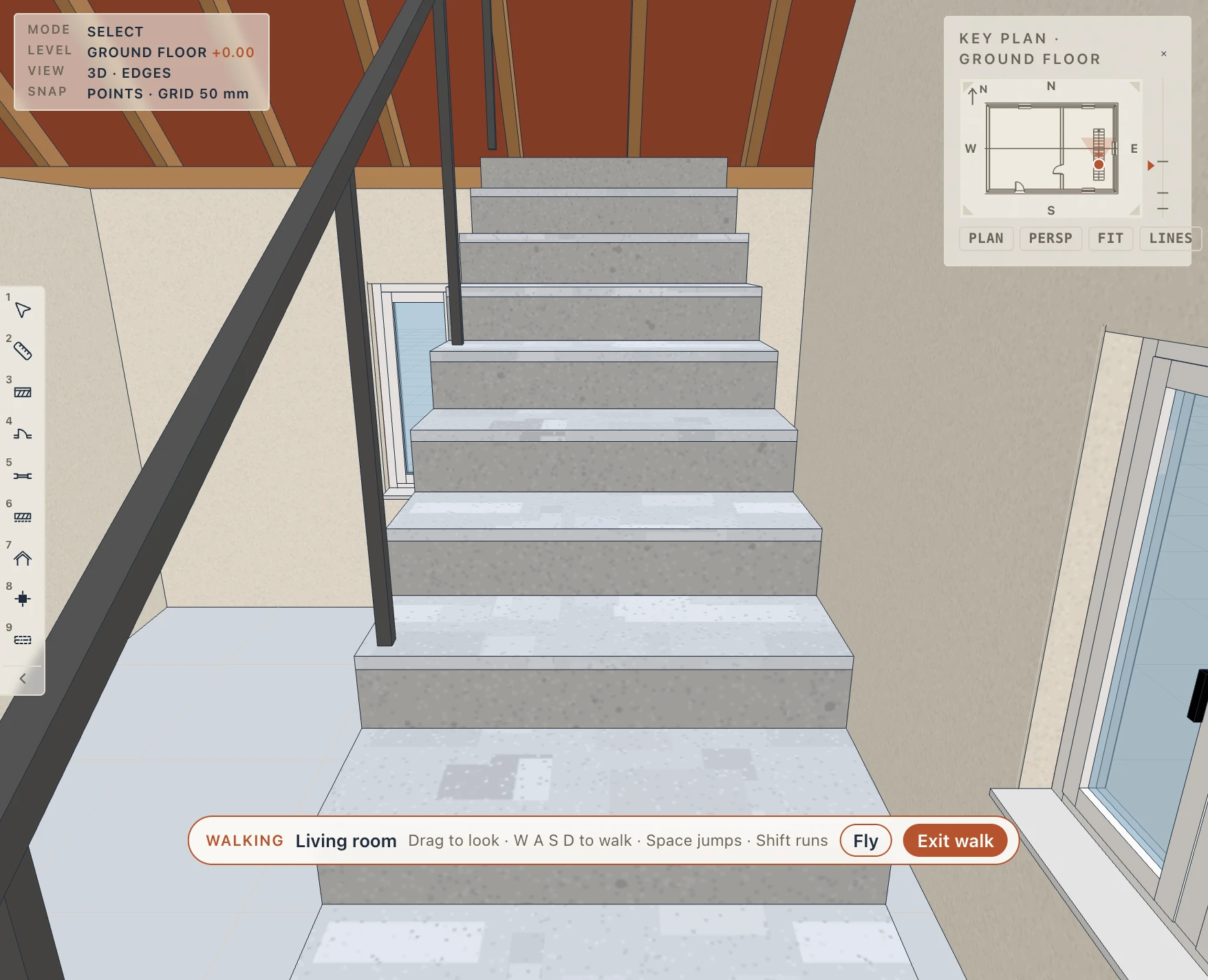
Fly in the walk's chip, or F, lets you fly instead: no gravity, and you pass through walls and floors. E and Q go up and down. Press F again to walk; you drop onto the floor under you.
Esc or Exit walk brings back the camera you had before.
Realistic, with the sun
View → Display quality sets how the 3D view renders, on this computer:
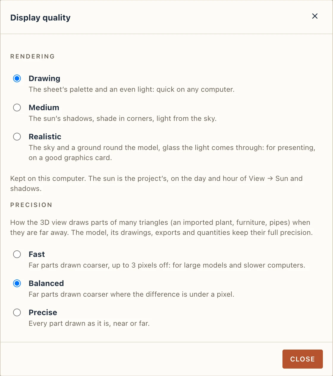
- Drawing: the sheet’s palette and an even light, as Lapin always drew. Quick on any computer.
- Medium: the sun’s shadows, shade in the corners where faces meet, and light from the sky.
- Realistic: the sky behind the model and a ground under it (where the project has no terrain), and glass the light comes through. For presenting, on a good graphics card.
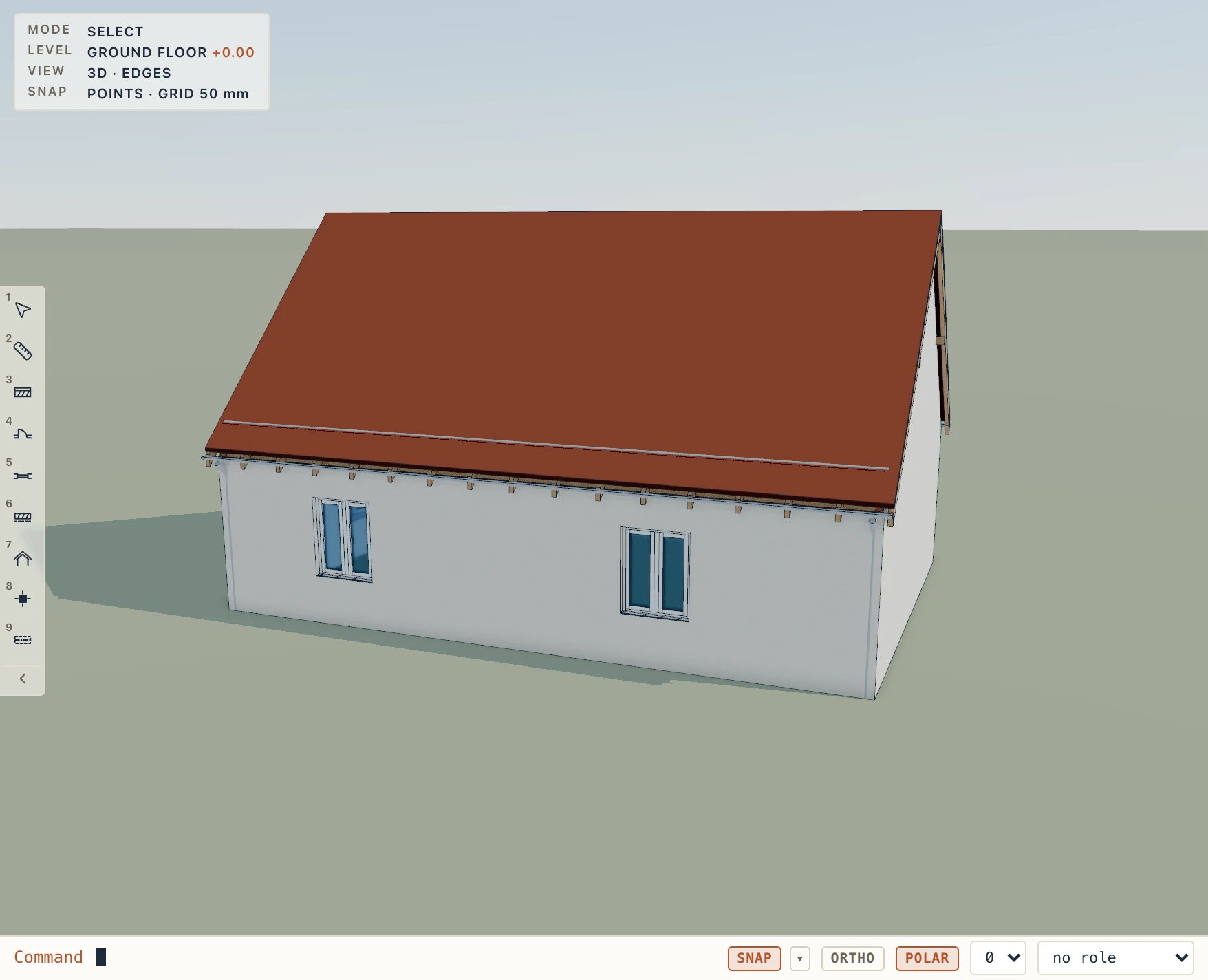
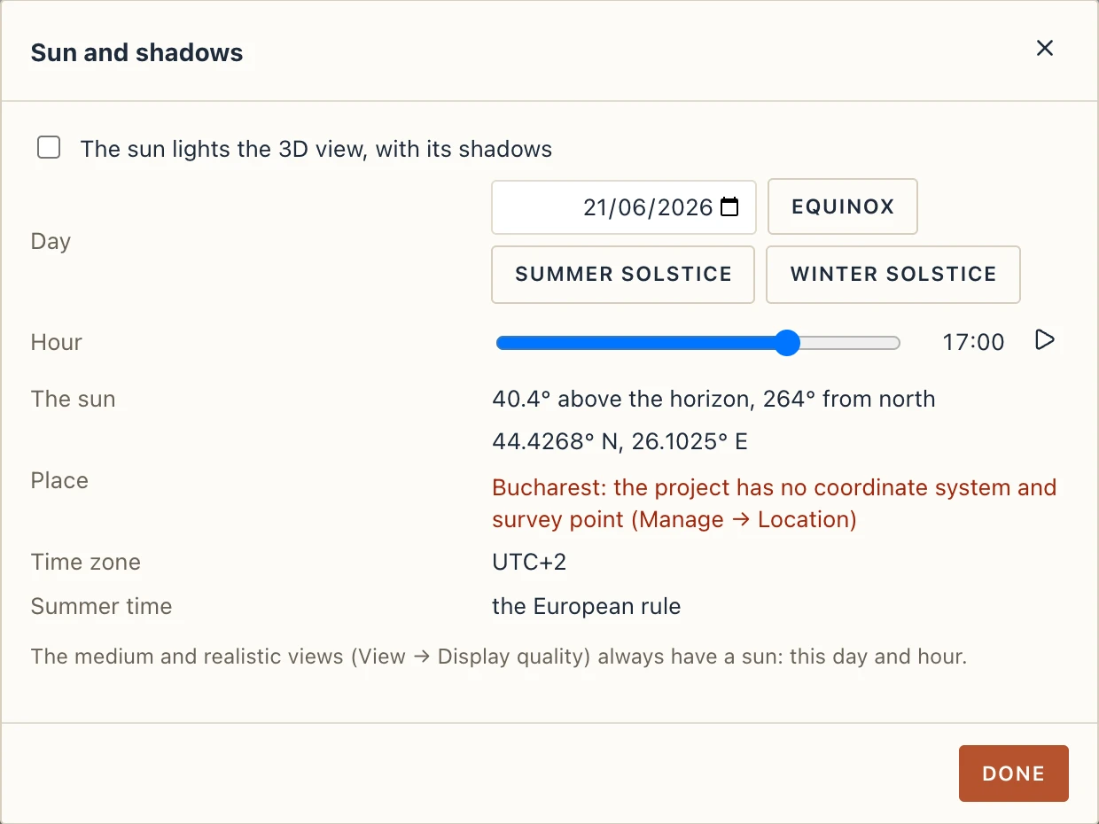
The sun is the project’s: where it stands for the project’s place (Manage → Location) on a day at an hour. View → Sun and shadows sets the day (the equinox and the solstices are a click away) and the hour, plays the day through, and turns the sun on in the drawing view too. Without a coordinate system and a survey point, the place is Bucharest. The time zone follows the place’s longitude, with European summer time in Europe.
The realistic view takes some of its numbers (the shade in corners, the shadows' quality, the sun's colour) from BimGo, by Aussie BIM Guru (MIT-0).
Modelling in 3D
The 3D view is a place to model in, not only to look: elements are moved and copied there as in a plan, snapped to the other elements' corners, edges and faces.
Moving and copying in 3D
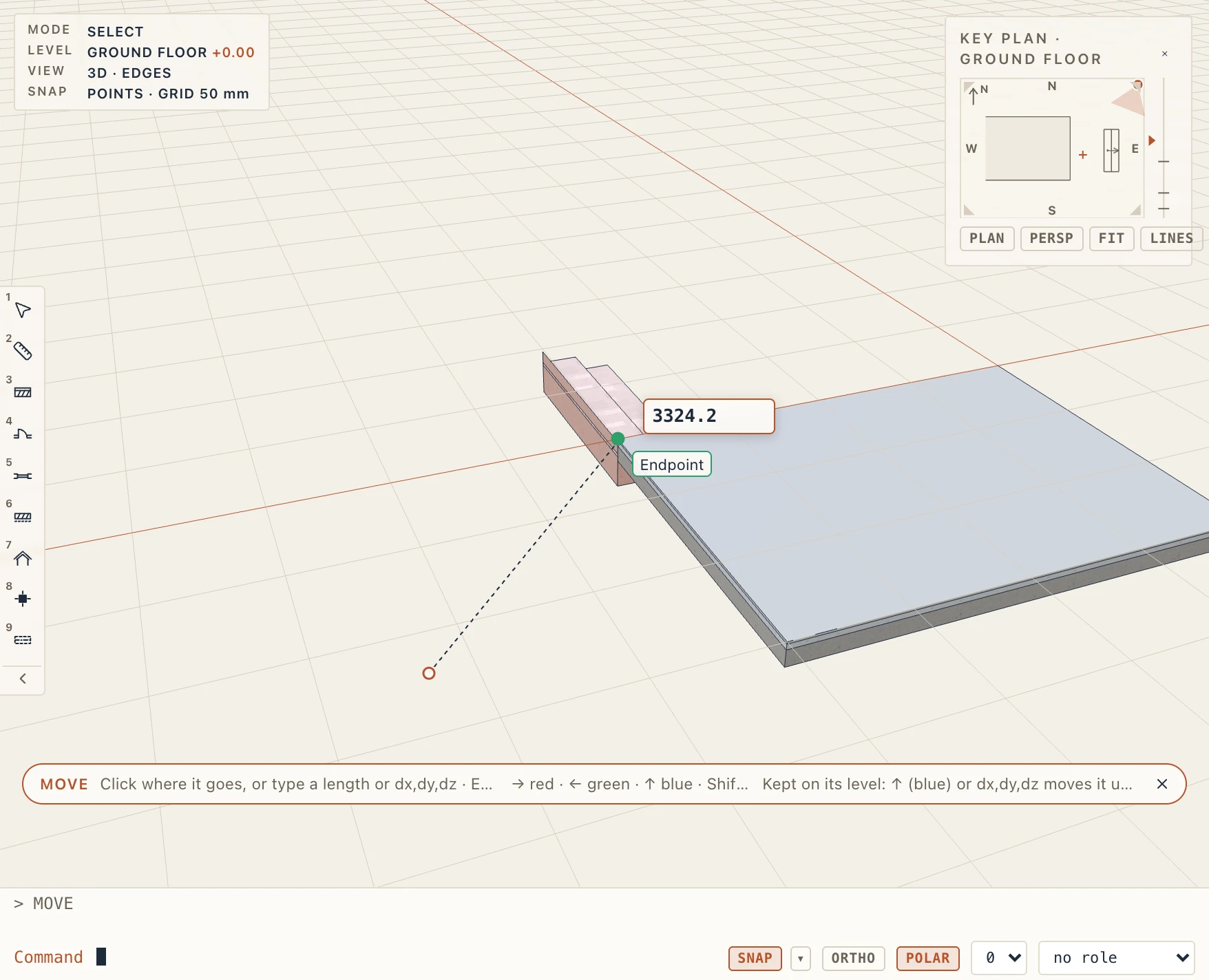
Select the elements, then Move (M) or Copy (CO) with the 3D view in front. Click the base point: a corner, an edge or a face of what you move. The cursor says what it snaps to: Endpoint, Midpoint, On edge, On face, or On level in empty space; what lies behind the face under the cursor is not taken. The lines of an imported DXF shown in 3D are snapped to as well. Then click where it goes, for example the corner of a floor: the selection follows the cursor in 3D, up and down too, and is placed there. From the base point the red, green and blue axes are inferred when the cursor runs along one; → ← ↑ lock the red, green or blue axis (the same key lets go), and Shift holds the axis inferred. With an axis locked, a corner hovered is brought onto the axis, to line the move up with it without going there.
Type a value at any time, without clicking a box: a length goes along the way the cursor points (1200), and dx,dy or dx,dy,dz is the displacement itself (0,0,450 lifts by 450 mm). Enter applies it, Esc cancels. Copy goes on copying from the same base point until Enter or Esc.
What has a height of its own goes up or down with the move: a wall's, a column's or an object's base, a stair's base and top (its rise kept), a beam's top, a floor's top offset, a roof's wall plate; a Studio solid takes a move step. A door or a window slides along its wall.
What stands on its level (a wall, a stair, a column, a floor, a beam, a railing, a roof, furniture, a door or a window) keeps its level when the move snaps from one point to another: it goes there in plan only, so a stair moved by its top corner onto a floor's corner does not climb the few centimetres between the stair's structure and the floor's finish (a stair's top already lands flush with the finish of the level it climbs to). To move it up or down, follow or lock the blue axis (↑), or type dx,dy,dz; the chip says when the level is kept. With nothing selected, Move and Copy ask for the elements: click them in 3D, then press Enter.
A drag in 3D always orbits the view, even when the cursor is on an element. To move a selected element by dragging it, press on it and hold still for a moment (the cursor turns into a move cursor), then drag: it moves the same way, from the point you pressed, snapped, and is placed where you let go. View → Drag to move in 3D turns this off, so that a drag on the selection orbits the view even after the hold.
Placing elements in 3D
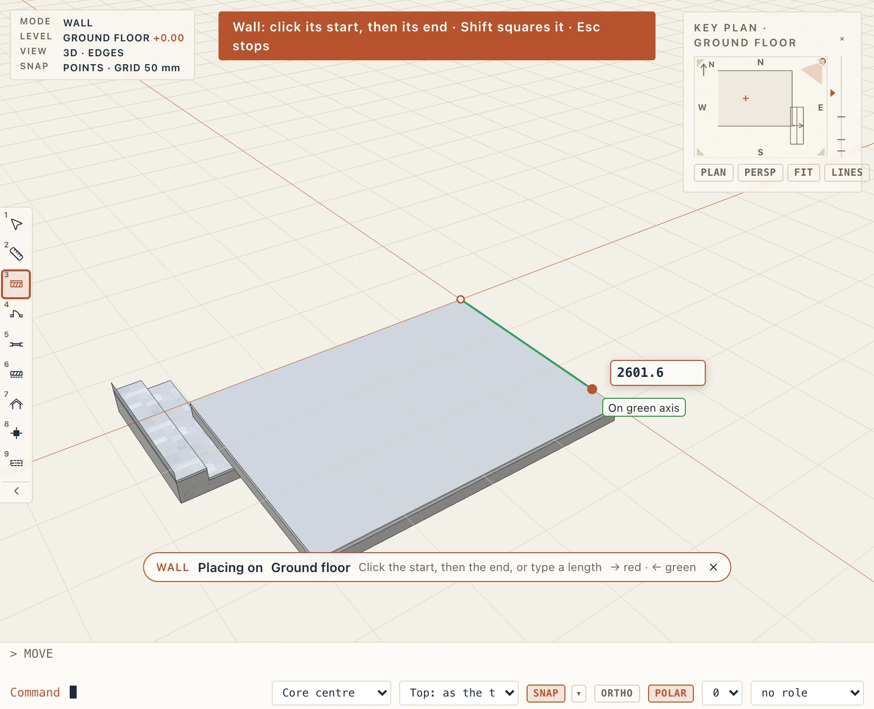
Every tool that takes points in a plan works in the 3D view too: walls, curtain walls, floors, roofs, ceilings, floor openings, rooms, columns, beams, footings, railings, skirtings, furniture, elevators, roads, plants and the rest. The points go on the active level: the cursor snaps to the model as a move does (a floor's corner, a beam's end, the middle of an edge, a DXF's lines) and the point is taken straight below it on the level, a dashed line showing where when it snaps above or below. The points and the outline they make are drawn on the level as you go: a wall's line, a floor's outline closing back to its first point, an arc through its third point. From the last point the red and green axes are inferred; → and ← lock them.
Type a value at any time: a length goes from the last point the way the cursor points (3000, or 3000<30 with an angle), a rectangle's width,height from its first corner. Enter applies it, closes a floor or ends a railing; Backspace takes the last point back; Esc drops the points, and again ends the tool. A drag still turns the view, so you can turn round the model between two clicks. The chip at the bottom says which level the points go on.
Doors and windows go where you click a wall's face in 3D, at the place along the wall you clicked.
Grips and components in 3D
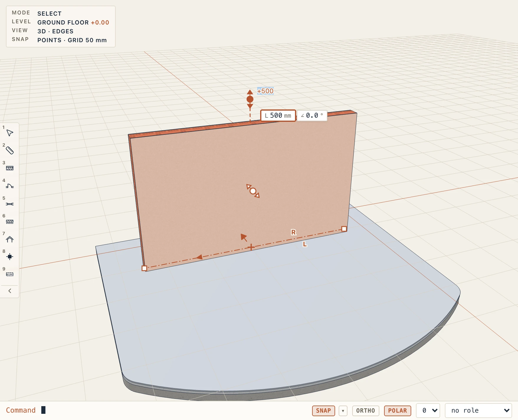
A selected element's grips (a wall's ends, a floor's corners) are dragged in 3D as in a plan, and snap as Move does: a corner first, then a middle, then an edge within reach, then the red and green axes through the grip's start, then a face. The point is marked and named at the cursor and taken at the grip's own height. Type a length or an angle while dragging, as in a plan; Enter puts the grip there.
Some grips are in 3D only, each with a small double arrow showing the way it moves:
- a selected wall's top (in the middle of its top edge): drag it up or down. A wall whose top goes to a storey changes its Top offset; an unconnected wall changes its height.
- a selected wall's two faces (half way up each side): drag across the wall to move it sideways; the walls joined to it follow. On a curved wall, the face grip changes the radius and keeps the centre.
- a selected floor's top: drag it up or down to change its offset from the storey (its thickness comes from its type).
- a selected roof's eave: drag it up or down to change its wall plate over the storey's top.
These grips snap to the corners, middles and edges of other elements, and the face grips to their faces too, so a wall's top can be taken to another element's height, or its face lined up with another face. While dragging, type a distance and press Enter; letting go is one undo step. Shift-drag an outline's edge middle to offset the whole outline (see Floors).
Drag a card from the Catalog or a tool from the ribbon onto the 3D view: its tool starts with that type. A tool placed by one click (a column, a pad footing, furniture, an elevator, a plant) is placed at once where you drop it, snapped to the model. Dropped, or clicked, on a floor of another storey, the element goes on that storey: a table set on the first floor's slab belongs to the first floor, whatever level is active.
Rotating a plan
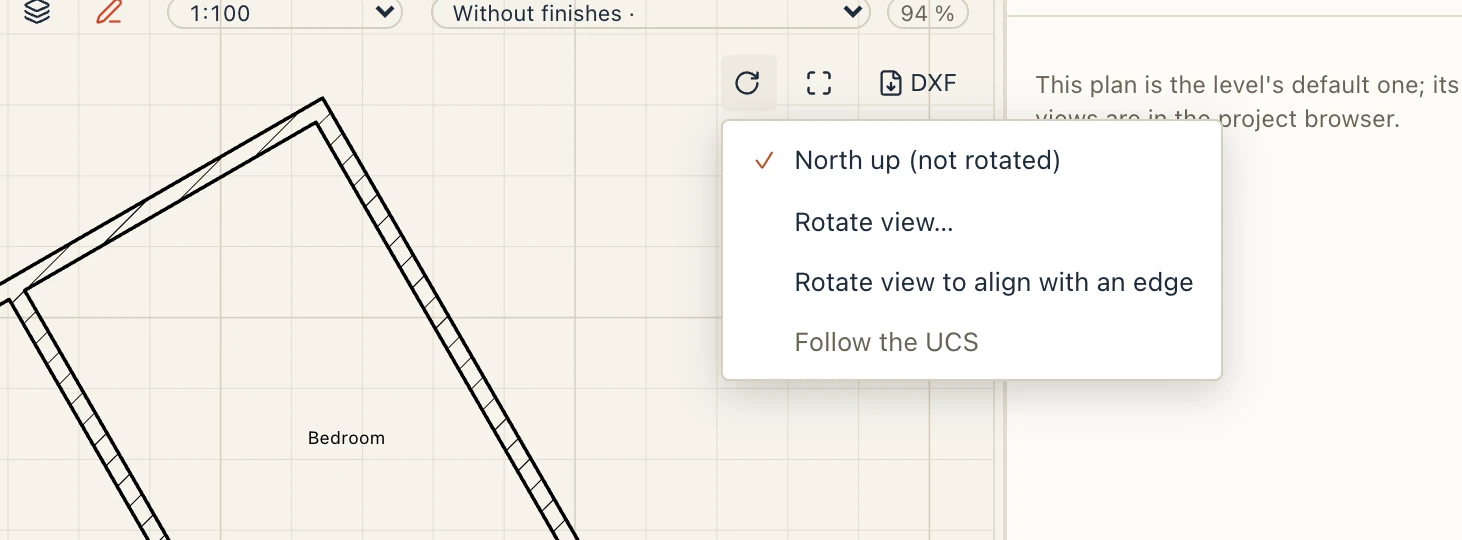
A plan can be turned so that a wall at an angle lies along the screen, as AutoCAD's PLAN, Revit's rotated crop and ArchiCAD's Set Orientation do. The plan's Rotate view button (the turning arrow in its bar) offers:
- North up (not rotated): the plan as drawn, its X axis to the right.
- Rotate view…: the direction to show horizontal, in degrees from the X axis (30 turns a wall drawn at 30° level).
- Rotate view to align with an edge: click two points, a wall's two corners for example; their direction becomes horizontal, turning the plan by at most 90°.
- Follow the UCS: the plan's horizontal is the UCS's X axis, and follows it when the UCS changes (see Snaps and helpers).
- True north up, when the project is turned from true north.
On the command line, PLAN asks for Current UCS (Enter), World (north up again), Angle, Edge or True north. Each change is one undo step. A level's default plan becomes its plan view when it is turned, with what was drawn on it.
The orientation belongs to the view: it is kept with the project and the view's sheets, its PDF and its DXF (in the plan's own coordinates) print it as the screen shows it. The DXF from the base point or in map coordinates stays in those systems. Everything else keeps working turned: pan and zoom, grips, snaps, the selection window and crossing, temporary dimensions, the key plan (which shows the turned screen on a north-up map) and the north arrow. Ortho, polar tracking and the grid follow the screen's axes, or the UCS's when one is set; typed coordinates stay in the UCS. Texts, tags, dimensions and room names turn with the plan and stay readable: a text that would read upside down is turned over where it stands, as drafting has it (upright within ±90°). Hatches turn as the drawing draws them.
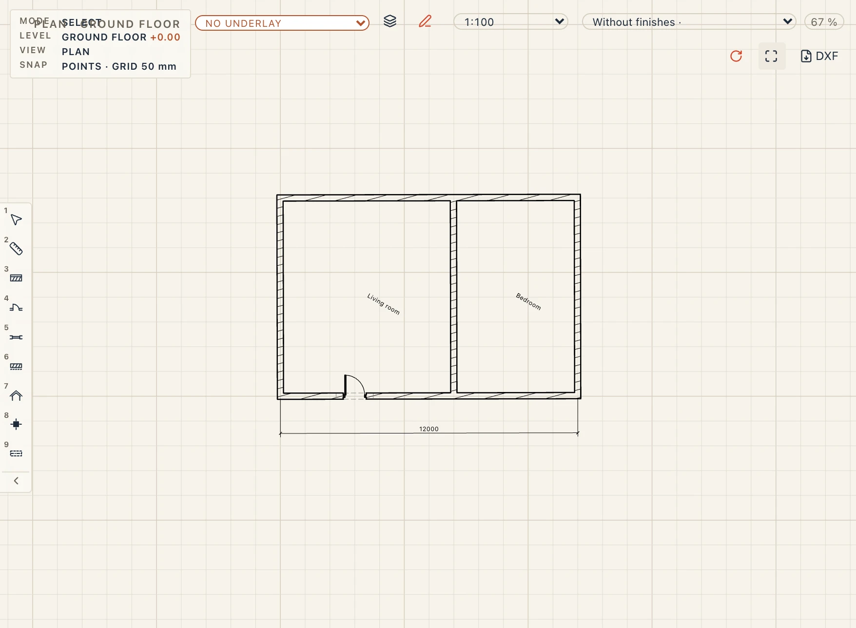
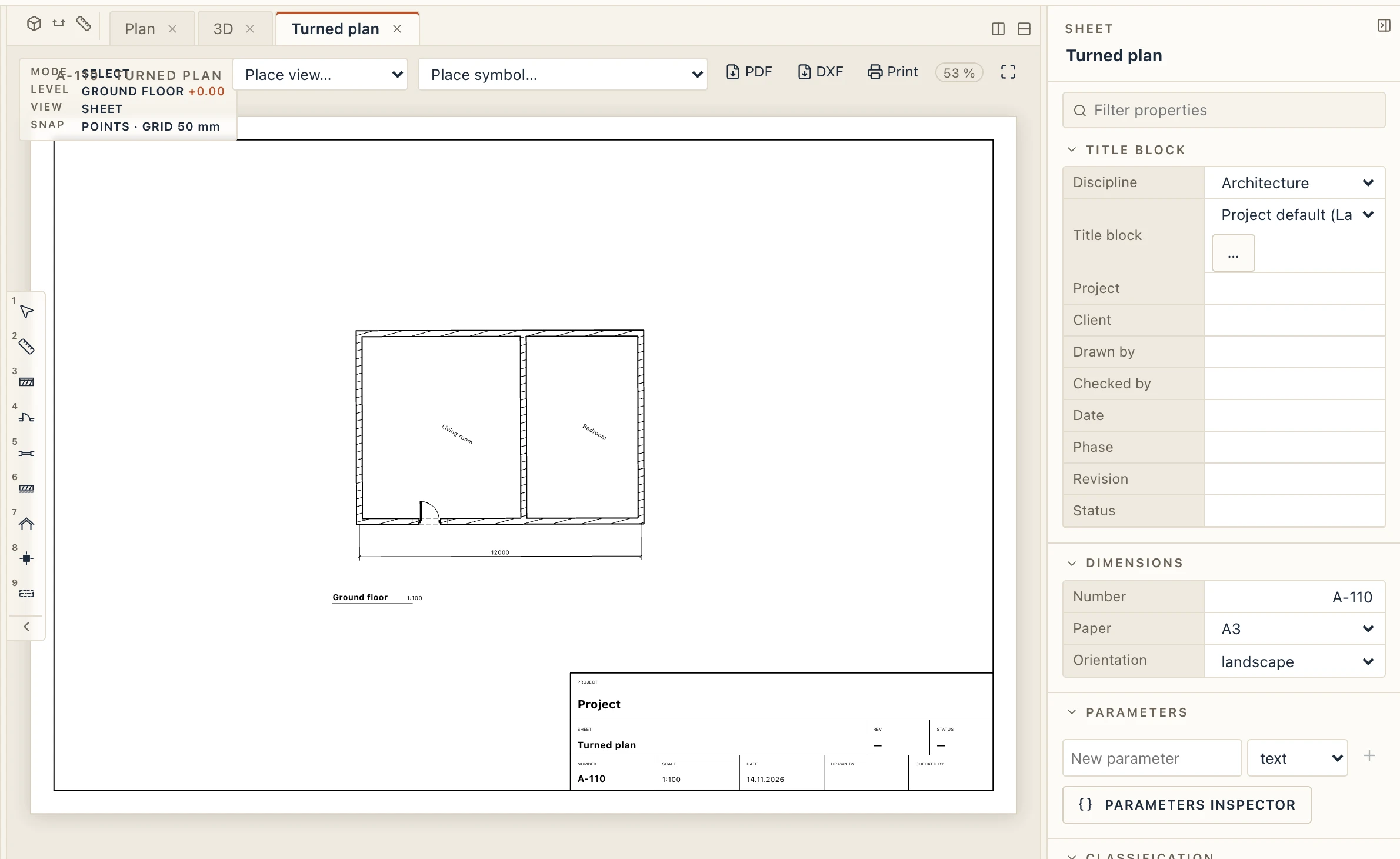
Only plans turn (floor, ceiling, foundation, site and location plans); a section or an elevation looks where its line or side says. A view boundary stays square to the plan's axes: on a sheet, a plan turned by other than a quarter turn shows the box round it, and the boundary is cropped in the view.
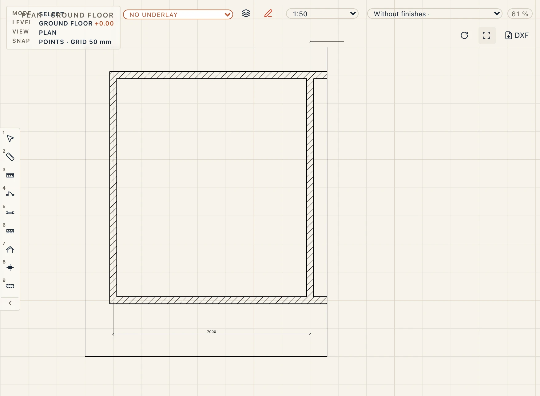
Crop region
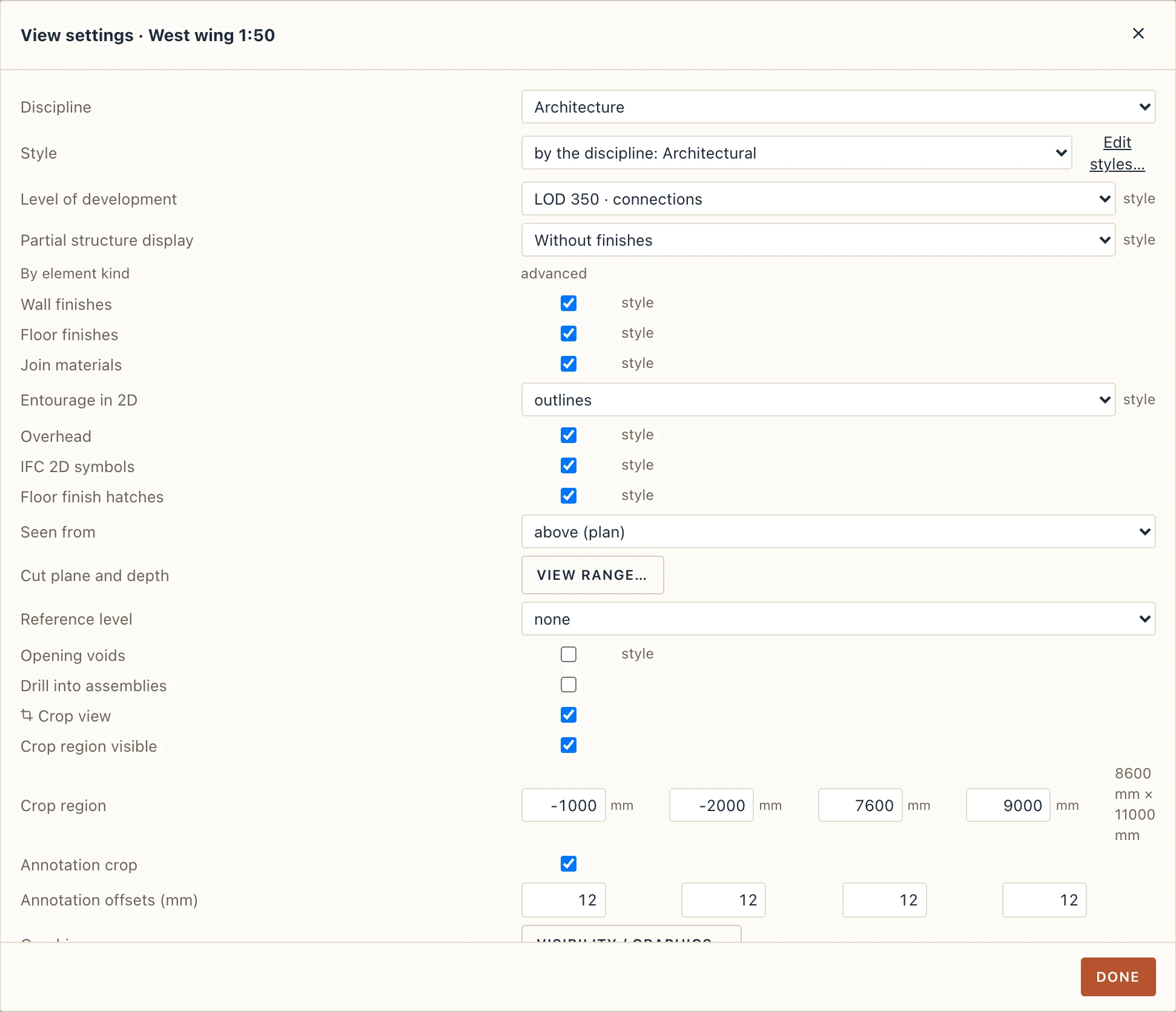
A plan, a section, an elevation or a reference plane can be cut to a rectangle, as Revit's Crop view does. In the view's View settings (in its properties, or View → View settings):
- Crop view turns the crop on or off. Turned on the first time, the region is drawn round what the view shows, with half a metre to spare. Only what lies inside it is drawn, the walls' and floors' lines and hatches cut at its edge; turned off, the view draws everything again and keeps the region for next time.
- Crop region visible draws the region's frame, on the screen and on sheets. Click the frame to select the view: its corners and edges have grips to drag, and its middle moves it whole. Hidden, the frame is not drawn or printed, and the view stays cropped.
- Crop region shows its corners (left, bottom, right, top) to type exactly, and its size.
- Annotation crop adds a second rectangle round the region, wider by the Annotation offsets (millimetres on paper: left, bottom, right, top; 10 mm each by default). An annotation (a dimension, a tag, a text, a symbol) wholly outside it is not drawn; one across its edge is cut there. Without it, annotations are drawn wherever they are.
Each change is one undo step. A level's default plan becomes its plan view when it is cropped, with what was drawn on it. The engine cuts the drawing, so the view's sheets, its PDF and its DXF print what the screen shows; on a sheet, the viewport is the crop region (the annotation crop when it is on), with no margin. A turned plan's region stays square to the screen. The 3D view keeps its section box instead.
Inset views
A detail often needs another view beside it at its own scale: a wall's section next to the plan, a node at 1:5 in a section at 1:50, a stair's plan in its section. View → Inset view (or type IV) draws any other view inside the one you are in, live: click where it goes, then choose the view in the list (every plan, section, elevation and reference plane's view, and each level's own plan). It is drawn there round your click, at the shown view's own scale, so it is the size it has on its own sheet, in a thin frame with its name and scale under it.
- It follows the model. The inset is the other view drawn as it is now: change a wall and both views change. An inset does not show the insets of the view it shows.
- Draw over it, and it goes on that view. A dimension, a text, a line, a rectangle or a bar drawn over an inset is put on the view the inset shows, in its own coordinates, so it fits what is drawn there and shows on that view too. In a plan, the annotation tools (Draft, Annotate, Simple rebar) do this; the model's tools (walls, floors) stay on the plan.
- Edit through it. What is drafted on the shown view is selected through the inset; its grips are where the inset shows them, and dragging one, or the shape itself, changes it on its own view, at its own size.
- Move it by its grip (its point), or with Move.
- Its properties (select its frame): View shown changes the view; Scale 1: gives it a scale of its own (empty: the shown view's); Framed draws or hides its frame and title; Pen weight, Line colour and Line type draw its frame as you choose (any of the project's line types, a dash-dot one too; default is the project's, see below); Crop cuts it to a part of the shown view: drag the crop's corners in the view. The shown view's own crop region is kept too.
Each change is one undo step. The engine draws the inset with the view, so sheets, PDF and DXF print it as the screen shows it, its lines cut to its crop, and what the shown view keeps for the screen (its reference planes) is left out on paper. Visibility / Graphics shows or hides insets with the callouts.
Detail callouts
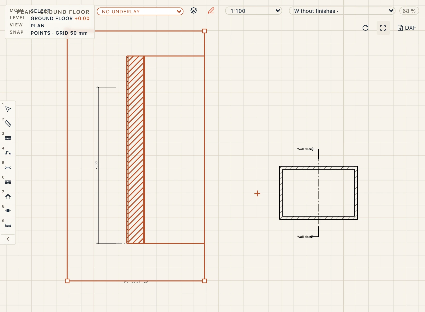
A foundation, an eave, a window's head: some parts need drawing again larger, with all their dimensions and notes. View → Detail callout (or type DC) calls out an area of a plan, a section or an elevation, as Revit's and ArchiCAD's callouts do: draw a rectangle round it (two opposite corners). The tool's bar draws a Circle (its centre, then a point on it) or a Polygon (its corners, then Enter) instead.
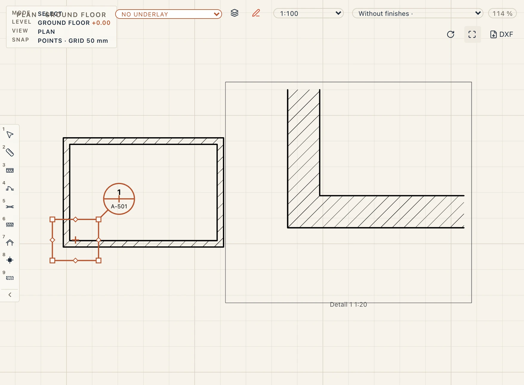
Lapin makes a detail view of it: a view of the same kind, with the settings of the view it was called from, cropped to the area, at a larger scale (1:20, or the project's next standard scale under the view's; choose another in the bar) and at the finest level of development. It is listed in the project browser under Details, named Detail 1, Detail 2 and so on (rename it as any view).
- It is a real view. Dimensions, texts, tags, drafted lines and hatches drawn in it stay in it, and its Visibility / Graphics is its own. Its model stays live: change a wall and the detail shows it. When the view it was called from changes its cut, its range or its line (a section moved), the detail follows; its scale, crop and graphics stay its own.
- The callout mark. The view you drew in shows the boundary, a leader and a head with the detail's number and its sheet: "3 / A-501" once the detail is placed on a sheet, "–" before. It changes by itself when the detail is placed, moved to another sheet or renumbered. Choose your own head in its Marker symbol (the Callout head slot, also for the whole project in Drafting standards); Lapin's Callout bubble writes the number over the sheet.
- Open the detail. Double-click the callout, or select it and right-click → Open view, or Open view in its properties.
- Reshape it. Select the callout: drag its corners, edges or middle (a circle's centre and radius, a polygon's corners) and the detail is cropped again; drag its head to move it off the boundary. Changing the detail's own crop in its View settings moves a rectangle callout with it.
- Refer to a view that is there. Choose a view in the bar's Refer to list (a drafting view, another detail) before drawing, or in the callout's properties: the callout points at it and makes no view, as Revit's reference callouts. The head writes that view's number and sheet.
- Delete it. Deleting a callout asks whether its detail view goes too, or stays. Deleting the detail view from the project browser takes its callouts with it.
- Its boundary's line. In the callout's properties, Pen weight, Line colour and Line type draw its boundary as you choose: a 0.5 pen, red, dash-dot, or one of the project's own line types (Drafting standards → Line types). default takes the project's.
The project's own default for both is in Manage → Drafting standards → Project: Detail callout boundary and Inset view frame, each its pen weight, colour and line type. A field left empty there is Lapin's own: a callout's boundary 0.35 black (grey and dashed while it refers to no view), an inset's frame 0.18 grey. A callout's or an inset's own choice goes before the project's; the head, its leader and the inset's title keep their colour. A standards file (.lapinstandards) carries the defaults, brought in with the project's options.
Each change is one undo step: drawing a callout makes it and its detail view in one. The engine draws the mark with the view, so sheets, PDF and DXF print it as the screen shows it; Visibility / Graphics shows or hides it with the Callouts. A circle or a polygon crops the detail to the rectangle round it.
What a view shows
The View tab sets what the view in front shows and how it looks.
Grid (F7) hides or shows the plan's background grid, and Thin lines (TL) draws every line one pixel thick, to read a dense drawing. Both are for the screen only: sheets, PDF and DXF keep their pens, and snapping to the grid stays. The 3D view's ground grid follows the same switch.

- View settings. The view's discipline and style, its range (the cut height and depth), and its graphics.
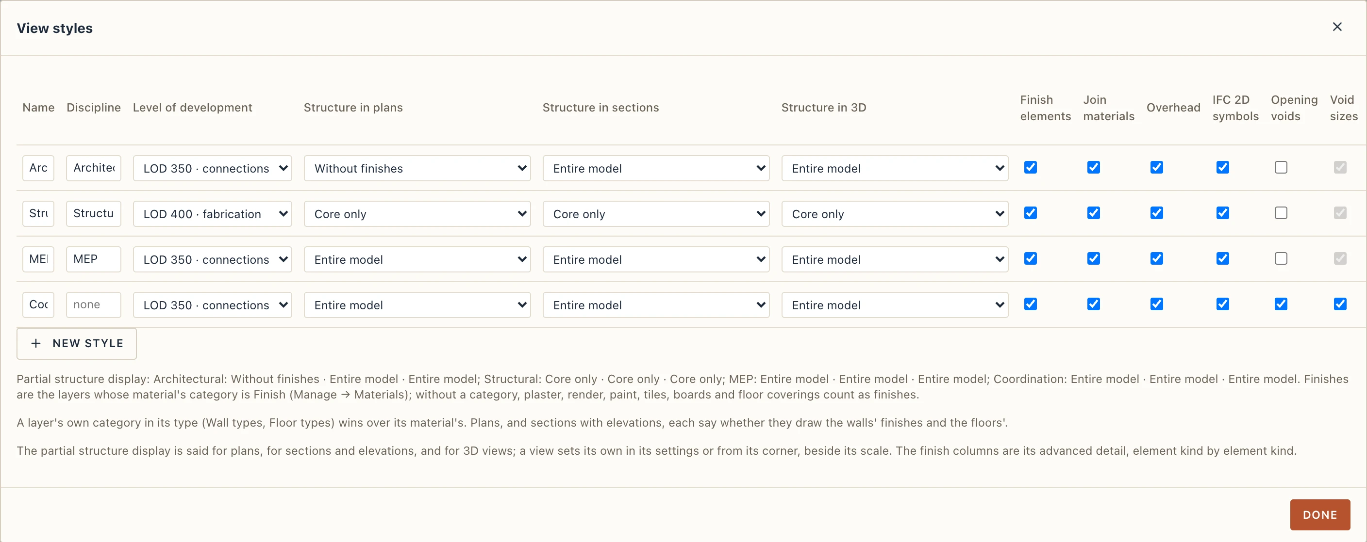
- View styles. Architectural, Structural (the cores only), MEP or your own. Each style chooses the layers drawn (its partial structure display, for plans, sections and 3D views apart) and how materials join.
- IFC 2D symbols. Elements imported or linked from an IFC file that bring their own plan drawing (a footprint, a door's swing, a fixture's symbol, with the file's colours, fills and texts) draw it in plans instead of their cut. Untick it in View settings (or in a view style) to draw their 3D cut instead.
- Visibility (VV) and Graphics (VG). They show or hide categories and set their pens, line types and fills.
- Split and Window. They show two views side by side, or open a view in a separate window.
- Display quality. How the 3D view renders (Drawing, Medium or Realistic, kept on this computer: see Realistic, with the sun), and how the 3D view draws parts of many triangles (an imported plant, furniture, pipes) when they are far away. Balanced draws a far part coarser only where the difference is under a pixel. Fast lets it stray up to 3 pixels, for large models and slower computers. Precise draws every part as it is. The precision belongs to the project. The model, its drawings, exports and quantities are never coarsened: a curve is made of straight pieces that stray at most a millimetre from it.
- Sun and shadows. The project’s sun on a day at an hour, lighting the 3D view with its shadows (see Realistic, with the sun).
Partial structure display
Each view says which layers of walls, floors and roofs it draws, as ArchiCAD's partial structure display does. Partial structure display offers four presets:
- Entire model: every layer, as built;
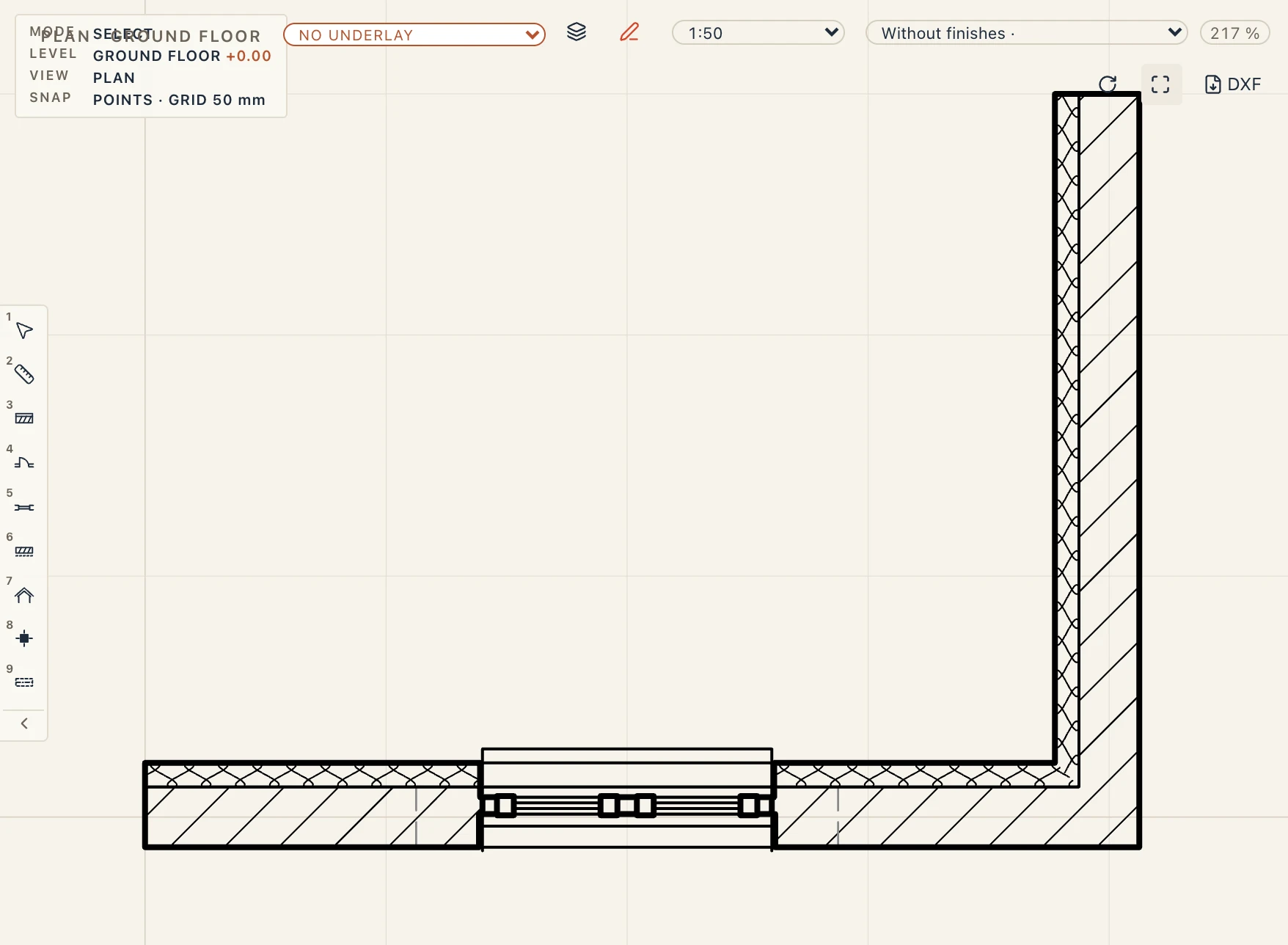
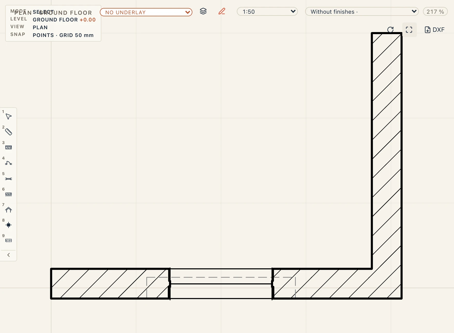
- Without finishes: the finish layers left out (plasters, renders, floor finishes and screeds whose Category is Finish), and with them the finishes laid as elements of their own: a room's floor, wall and ceiling finishes, skirtings, a covering that is a flooring, a cladding or a ceiling, and a linked element made all of a finish material; the insulation, the membranes and the structure are drawn;
- Core only: the cores alone, between their boundaries; the insulation goes too, and so does an element made all of insulation or of a membrane;
- Core of load-bearing elements only: the cores of the load-bearing elements alone. An element that bears no load (a partition, a covering, a room's finishes) is not drawn at all, and the doors, windows and openings of a wall left out go with it. A wall bears load unless LoadBearing is unticked in its properties (Pset_WallCommon), on it or on its type, or its IFC type is a partition (PARTITIONING): so a wall that says nothing is drawn, and the preset is of use before every wall is marked. Untick LoadBearing on your partition types. Columns, beams, footings, floors and roofs bear load unless they say they do not. The structural analysis keeps its own rule: there a wall bears load only when LoadBearing is ticked, and the others are partitions whose weight goes onto the floors (see Loads).
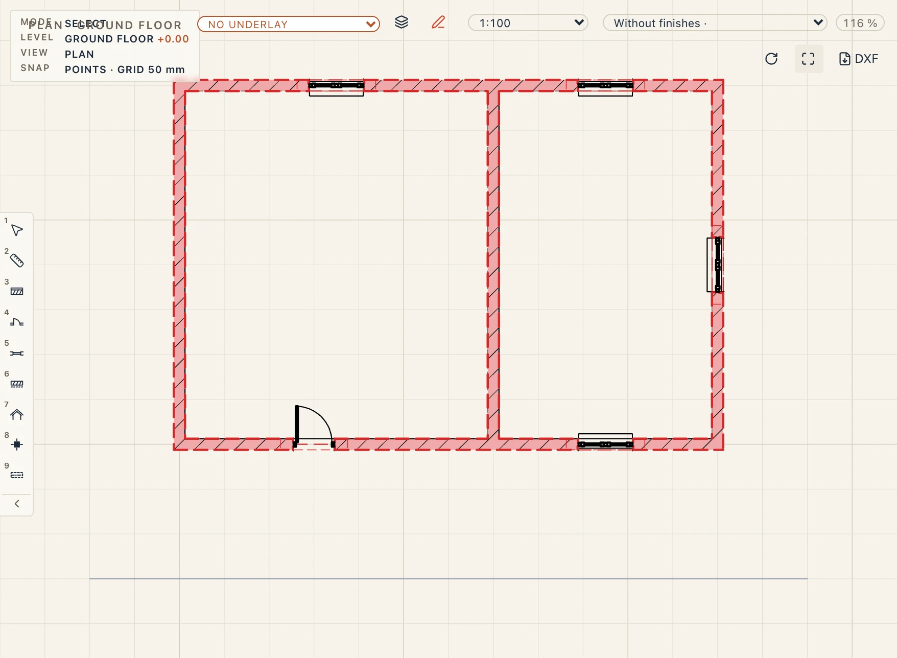
A finish is a layer whose own Category in its type is Finish, else whose material's category is (Manage → Materials). In a new project, plans are drawn without finishes, and sections, elevations and 3D views show the entire model, the classic set for architectural sheets: the plasters left out of plans while the thermal insulation shows, sections and details with everything. A project made before draws as it did.
Manage → View styles sets it for each style apart: Structure in plans, Structure in sections (sections and elevations) and Structure in 3D (3D views and the rest), so every view of the style follows. A view sets its own in View settings, and the button beside it takes the style's again. It is also at the top of a plan, a section or an elevation, beside the scale: pick another preset there, in one step to undo. On a sheet, pick a placed drawing and its preset shows there too, so each drawing on a sheet says its own. A level's plan with no view of its own becomes the level's plan view with it.
A plan applies it to what its cut plane cuts: a floor seen under the cut shows as it is, with its finish on top, and so do a room's floor finish and its skirtings, while the rooms' wall finishes the plane cuts are left out. Sheets, PDF, DXF and the snaps follow what is drawn: a plan without the wall finishes snaps to the cores' faces. The model is unchanged: quantities and IFC keep every layer and every finish. A project made before draws its rooms' finishes and skirtings as it did: tick Finish elements in Manage → View styles to leave them out with the finish layers, as a new project does.

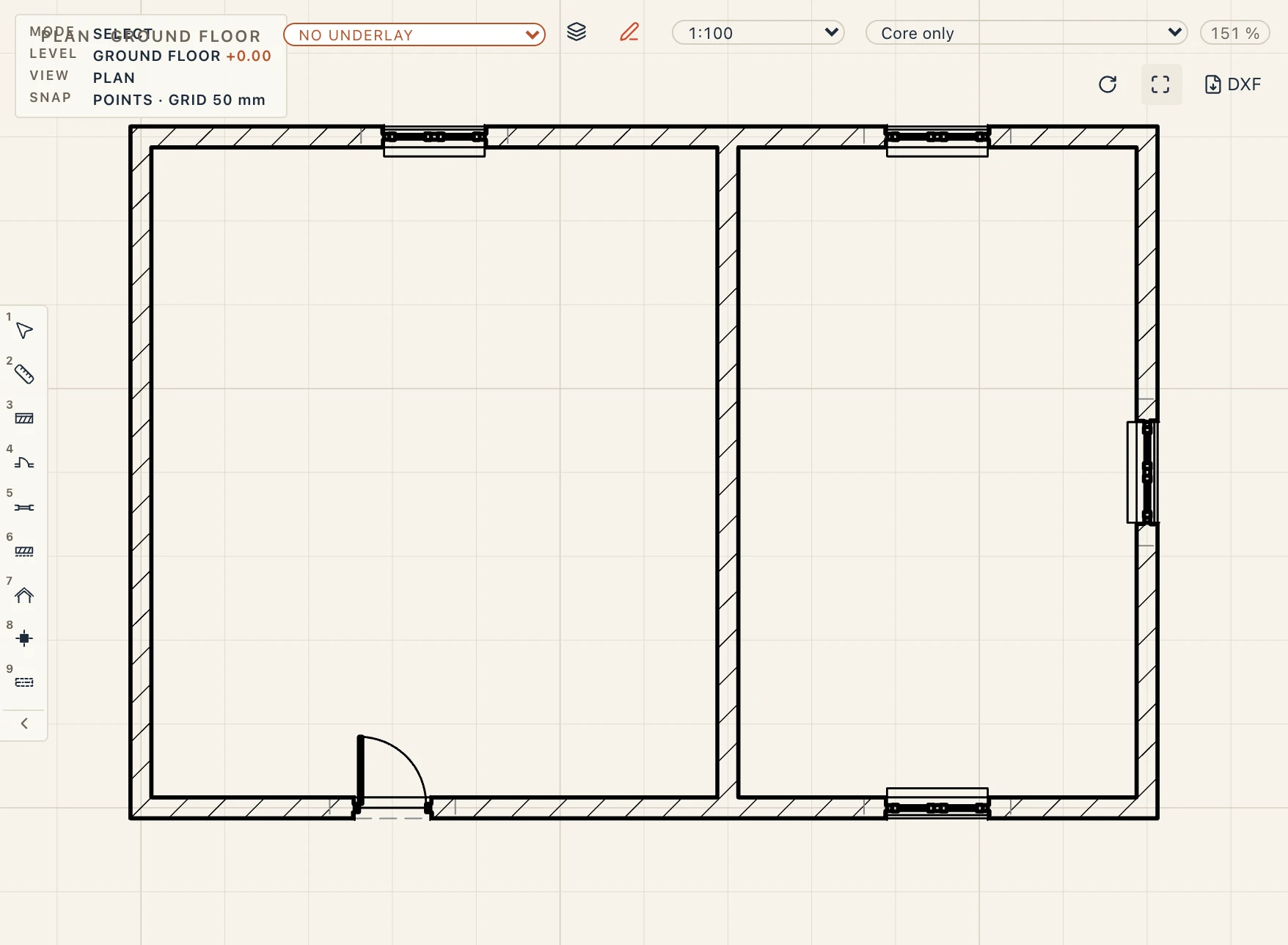
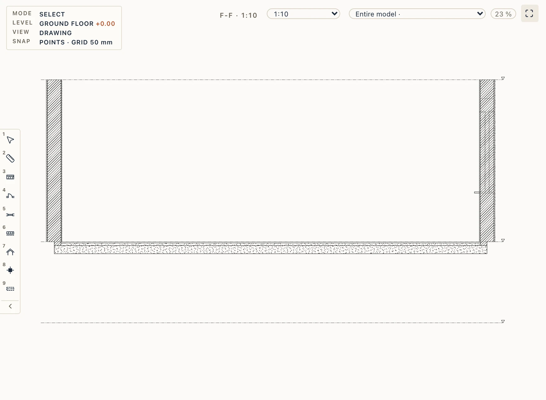
By element kind. Under the preset, View settings of a plan, a section or an elevation has Wall finishes and Floor finishes, and Manage → View styles has Wall finishes in plans, Floor finishes in plans, Wall finishes in sections and Floor finishes in sections: unticked, the view also leaves out the walls' or the floors' finish layers (and the rooms' wall or floor finishes) whatever its preset. All are ticked by default. Polish drawings, for example, are printed with plans without any finishes and sections with the floors' finishes but not the walls': plans Without finishes, sections Entire model with Wall finishes in sections unticked.
Visibility / Graphics
Visibility (VV) or Graphics (VG) opens the view in front's Visibility / Graphics, for a plan, a section, an elevation or a 3D view. What it hides is hidden on the view's sheets, in its PDF and DXF, and in a 3D export too.
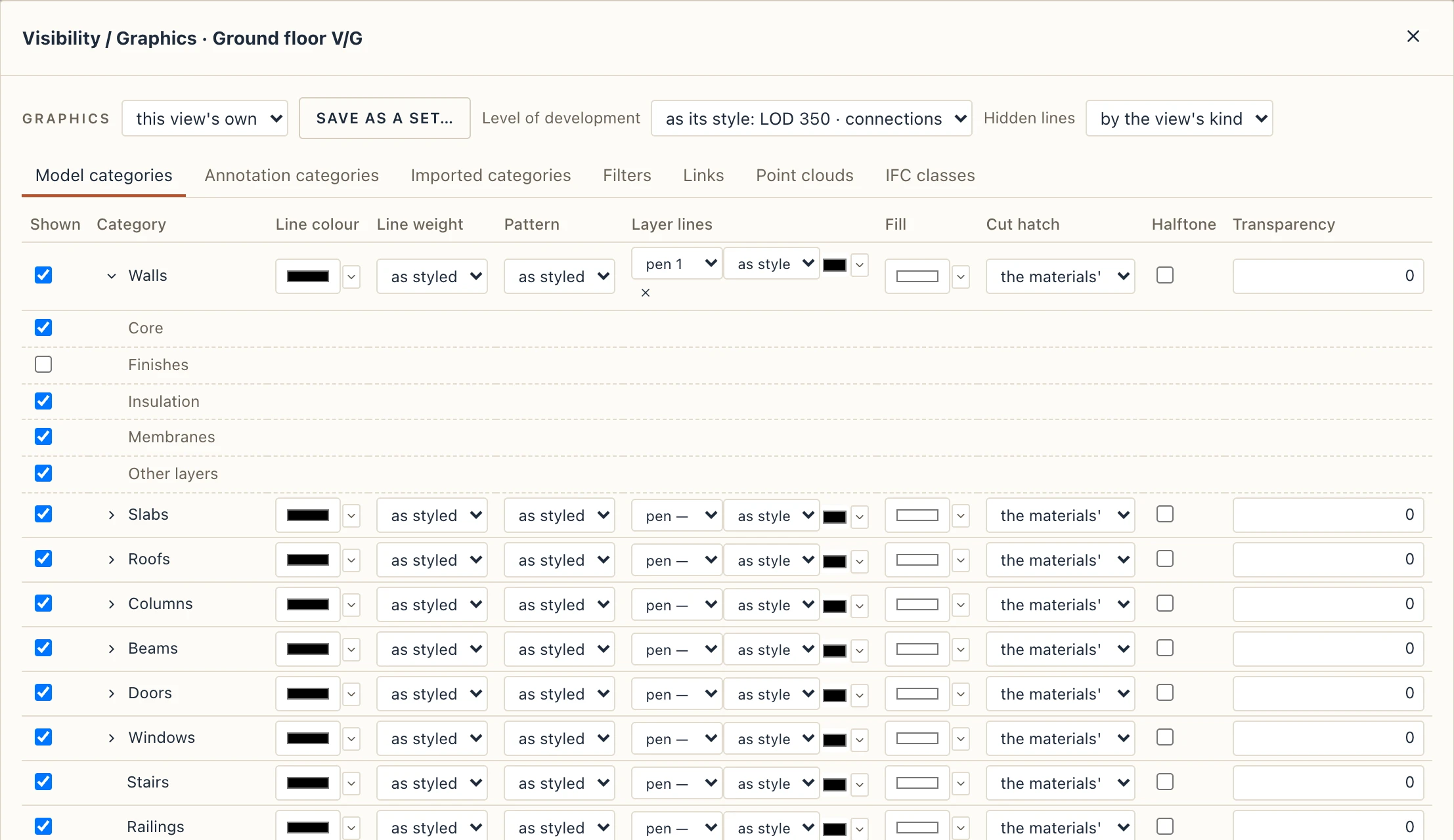
- Model categories. Each category is shown or hidden, with its line colour, line weight, fill and cut hatch. The arrow beside a category opens its subcategories: a wall's, a floor's or a roof's Core, Finishes, Insulation, Membranes and Other layers (by each layer's material and its category in Manage → Materials), a door's or a window's Reveals. Untick Finishes under Walls and the plaster goes, the brick stays. Rebar, room finishes (Coverings), formwork, scaffolds, MEP, steel connections, elevators and sunshades are categories of their own.
- Layer lines. The lines drawn between the layers of a cut element (a wall's plaster and brick, a floor's screed and slab) have their own pen (from the pen table), line type and colour, in the Layer lines column of a category; the contour keeps the cut lines. Left empty they draw as before: thinner than the contour, or as the category's cut lines when those are set (× sets them back). For the whole project, Manage → Object styles has a Layer lines column beside Cut and Projection; a view's setting wins over it.
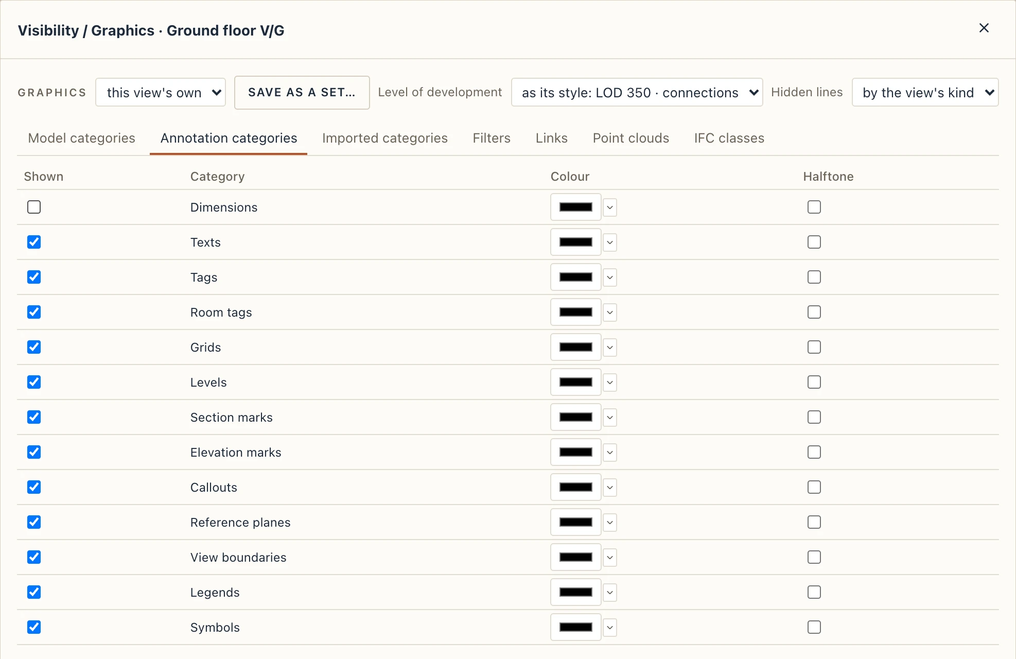
- Annotation categories. Dimensions, texts, tags, room tags, grids, levels, section and elevation marks, callouts, reference planes, view boundaries and legends, each shown or hidden in this view.
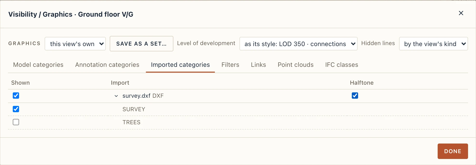
- Imported categories. Each DXF imported into the view, by its file: shown, halftone, and its layers one by one (the arrow beside it). A PDF or an image traced over the view is shown or hidden here too.
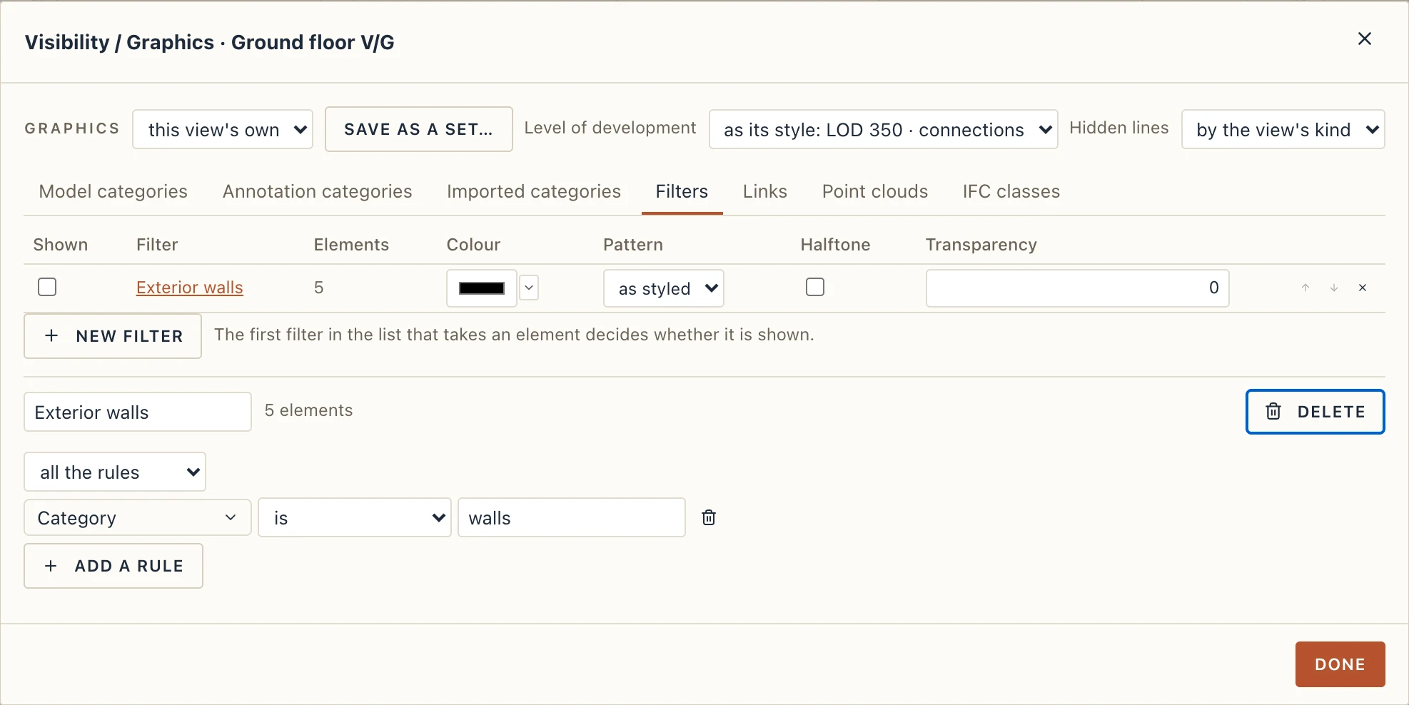
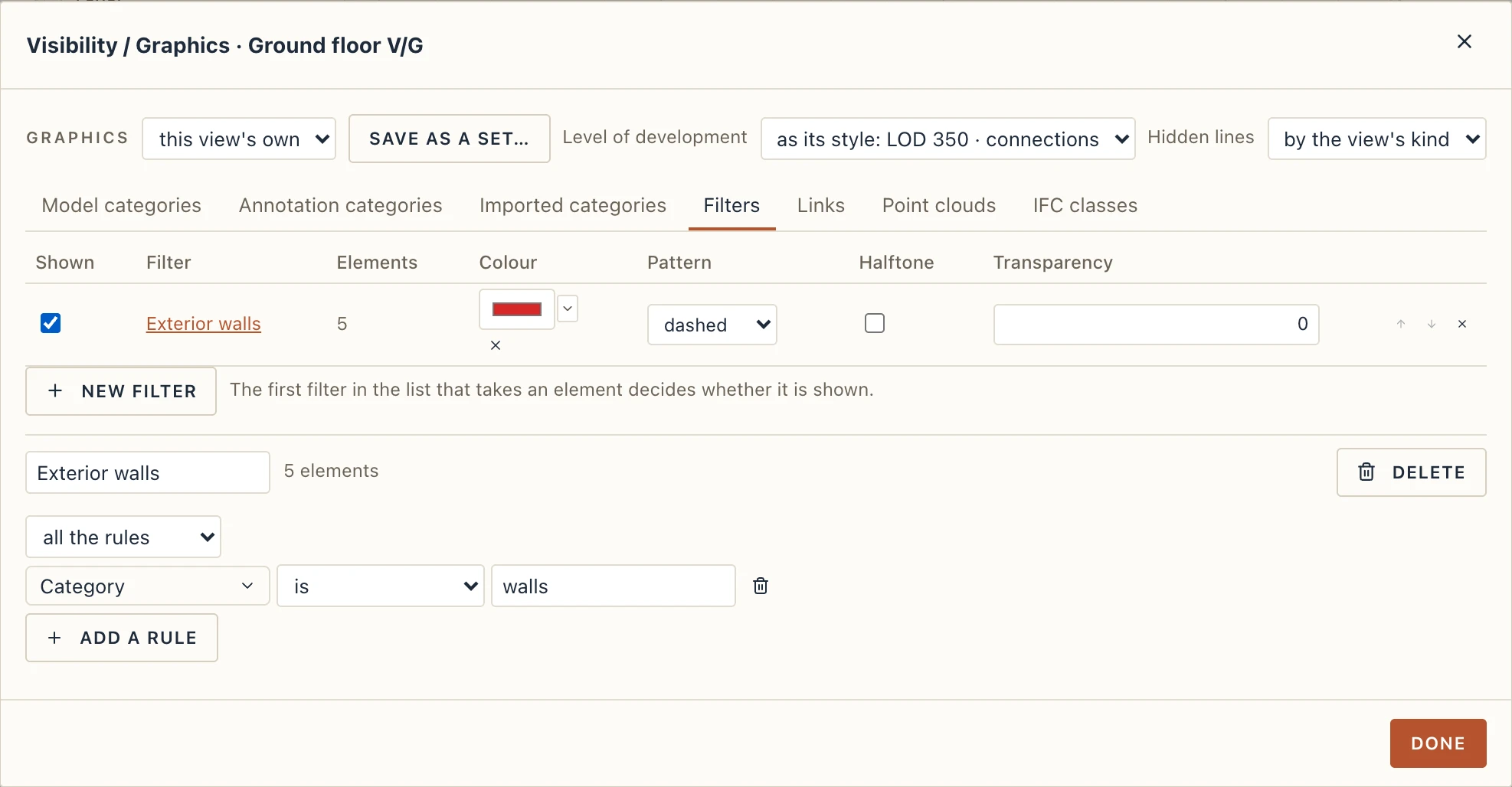
- Filters. Rule-based, as in Revit: New filter, then its rules, in the editor Quick select uses (see Quick select): an element's IFC class, category, type, name, material, storey, group, linked file, phase created or demolished, predefined type, a parameter as text, such as Fire rating or Pset_WallCommon.IsExternal, or any field of the project; is, contains, starts with, is greater than, is between, is one of, has a value…; all of them or any. The view uses the filters in its list, in order; the first that takes an element decides whether it is shown. Manage → View filters opens this tab.
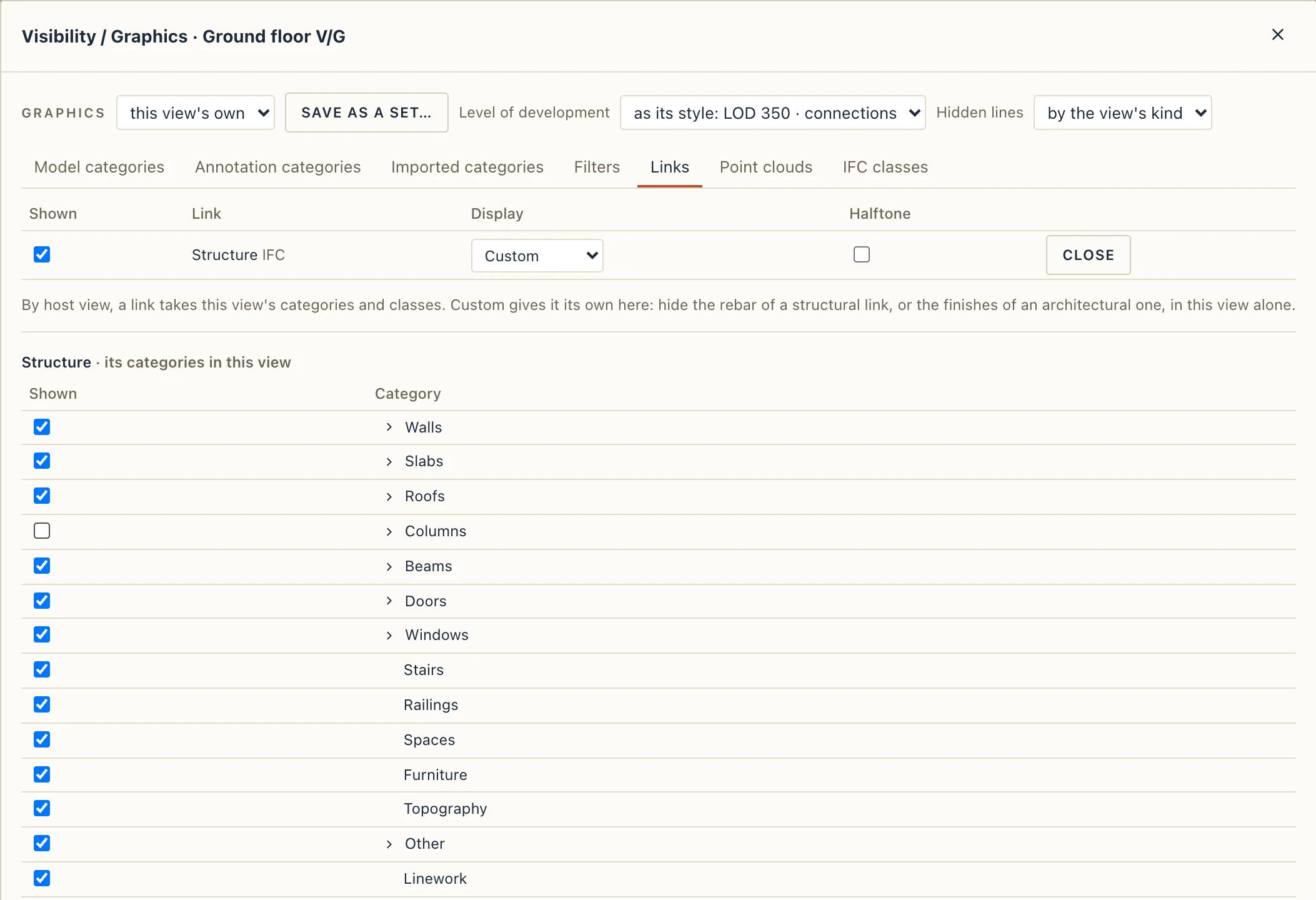
- Links. Every linked file, with Shown and Halftone for this view alone. Display is By host view (the link takes this view's categories) or Custom: then Categories… gives the link its own categories, subcategories and IFC classes in this view. An architect's plan hides the structural link's rebar; an engineer's hides the architectural link's finishes.
- IFC classes. The classes of the project's own elements, shown or hidden.
- Graphic overrides. A category also takes a Pattern for its cut and projection lines, Halftone and a Transparency (in 3D, 0 opaque to 95); an annotation category a Colour and Halftone; a filter a Colour, a Pattern, Halftone and a Transparency for what it takes, the first filter in the list giving each. Detail level is the next item.
- Level of development. A way of viewing, never taken from the scale: a view draws at the level its style gives it (Manage → View styles: 350, a structural style 400) or at its own (View → View settings, or the head of Visibility / Graphics, a 3D view's too). LOD 100 (massing) draws walls, floors and roofs as one outline hatched as their core, steel members as a single line on their axis, and a door or a window as its opening and its swing; LOD 200 (layers) adds the layers, and the frames and sashes of doors and windows simplified (no glazing bars, no hardware); LOD 300 (details) their full profiles and their details (reveals, sills, surrounds, thresholds, window boards, hardware, shutters, grilles) and the openings' linings; LOD 350 (connections) the steel connections' plates, bolts and anchors; LOD 400 (fabrication) a linked structural model's reinforcing bars and the real section of steel members: root fillets, toe radii, sloping flanges. A project made before keeps how its views drew: each view gets the level its scale gave it then (1:50 LOD 400, 1:100 LOD 200, 1:200 LOD 100), a 3D view LOD 400. A linked or imported IFC's walls and floors split by the layer sets their file gives them, so their Finishes, Insulation and Core hide as a native wall's and the Structural style's cores-only drawing reaches them; a wall's plaster brought as a part of its own, or a covering of one finish, goes with Finishes. Every 3D view leaves Rebar out until it is shown.
The settings belong to the view, or to a named set that several views share (Save as a set…). A view style can name a set (Manage → View styles): a view with no settings of its own takes its style's set, as Revit's view templates do; Make them this view's own starts its own from it.
Point clouds in views
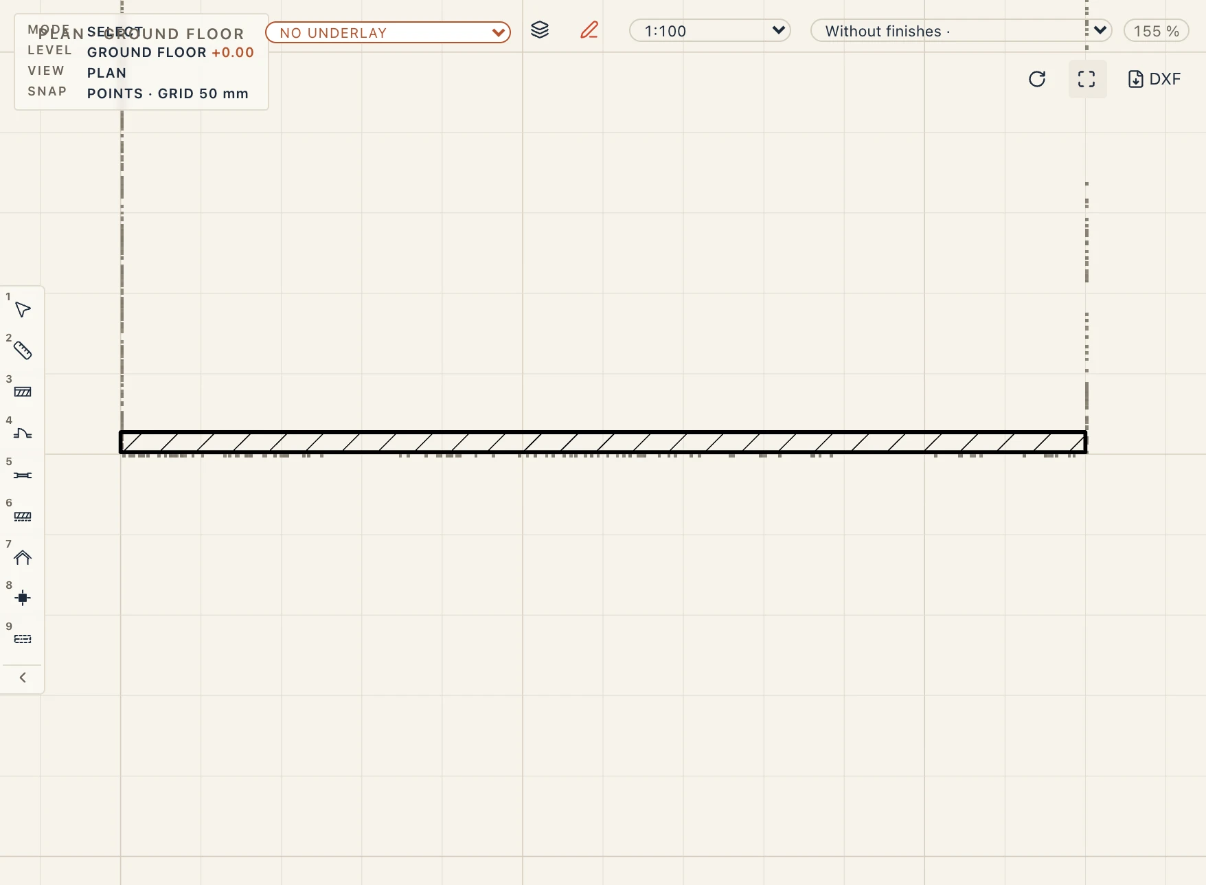
A linked point cloud (Import and export, Point clouds) shows in every view. A plan draws the slice its cut takes, 10 cm round the cut plane, as dots under the walls; a section the slice just behind its plane; an elevation every point it faces, the nearest in front. The dots are the scan's own colours, darkened to read on paper, and they print on sheets and in the PDF as the screen shows them. Their points are snaps: draw walls over a scan's slice and they land on its faces. In the 3D view the placing tools and Move snap to the cloud's points as they do to corners. A new plan opens framed on the model, or on the cloud's slice when it has nothing else; only the part of the slice on the screen is drawn, so a scan of a whole district stays quick zoomed in on one building.
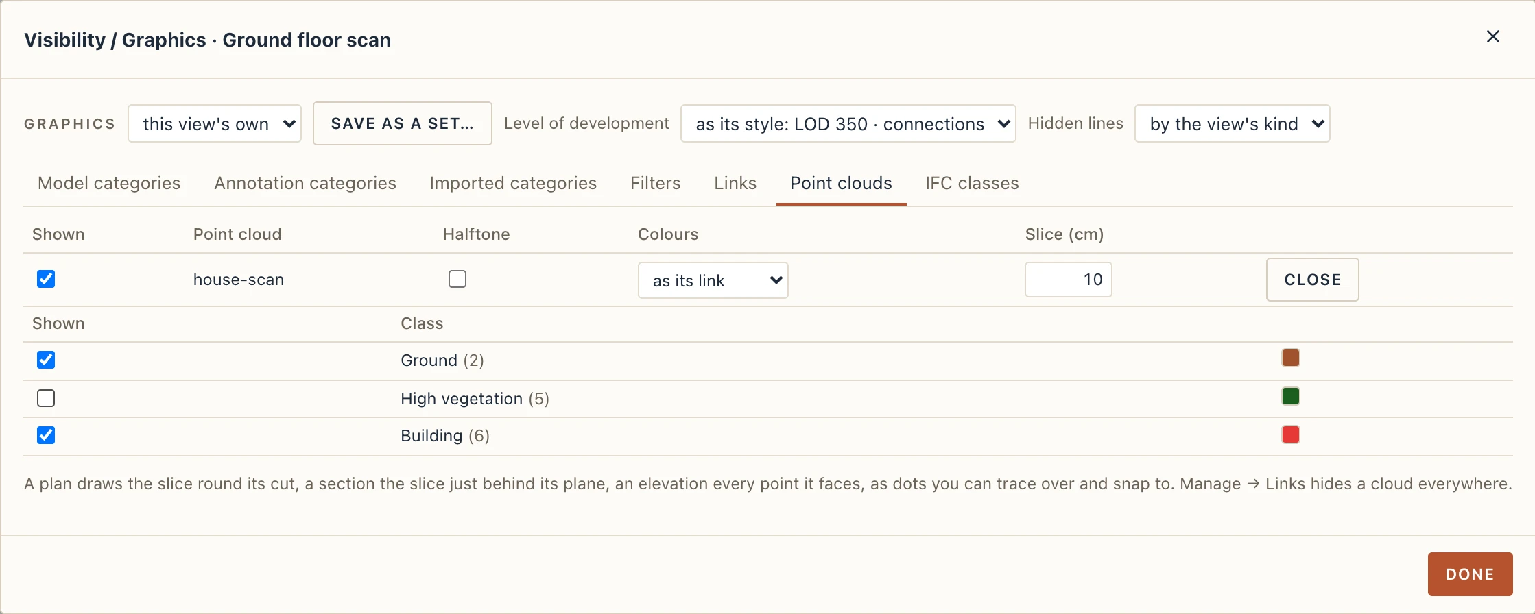
Visibility / Graphics (VV) has a Point clouds tab: per cloud, for this view alone, Shown, Halftone, its Colours (as its link, RGB, intensity, elevation or classification), the Slice a plan or a section draws (cm, up to 100 m: an airborne scan's facades need a thick slice), and Classes…: the ASPRS classes its points have (ground, vegetation, building, noise…), each shown or hidden. A 3D view's tab rules what the 3D draws. Export 3D… takes a sample of the clouds shown (at most 5 million points) as points in GLB and glTF when Point clouds is ticked; no other export carries them.