User guide
Drafting and the command line
Type commands as in CAD, snap to points, move and copy, draw lines, and annotate with dimensions, text and tags.
The command line
Type a tool's letters anywhere in the window, then press Enter. For example, type WA for a wall, CO to copy, M to move, or L for a line. The command line at the bottom shows what the tool needs next. You can click a point or type a length, an angle or coordinates.
Typed coordinates are in the project's unit, as the lengths beside the cursor are: in a project in millimetres, @4000,4000 after the first corner of a rectangle makes it 4 m by 4 m, and 4000<90 is 4 m straight up.
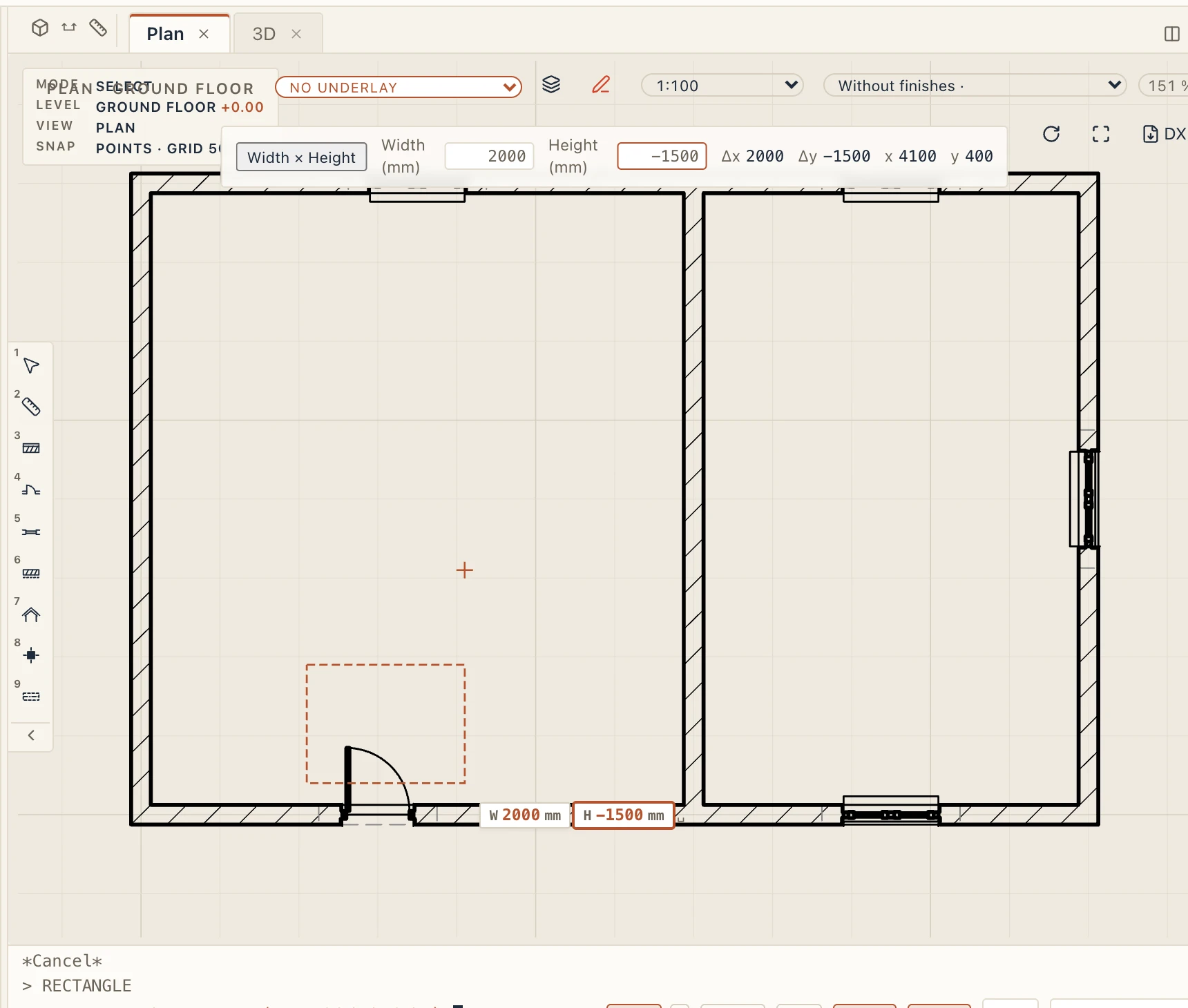
The box by the cursor. While a segment is drawn, the small box beside the cursor shows its Length and ∠ angle, and you can type into it without clicking anywhere: the digits (with a unit, if you like: 240cm, 2.4m) go to the focused field, Tab moves to the other, Enter takes the point and Esc clears what you typed. For a rectangle (the drafting Rectangle, a floor or any other tool that is drawn as one) the box can also ask for the Width and Height instead, like @2000,1500 on the command line: press Space (or click the mode button in the bar over the view) to switch between Length ∠ Angle and Width × Height. In Width × Height, Tab or a comma goes from the width to the height, and the values are signed as on the command line: a negative width puts the rectangle to the left of the first corner, a negative height below it. A field left empty follows the mouse. Each rectangle tool remembers its own mode. A click takes what is typed, as Enter does: type 145 after the first point of a copy, then click, and the copy lands 145 away along the direction of the click (the click gives only the direction; with width and height, only the sign of an empty field).
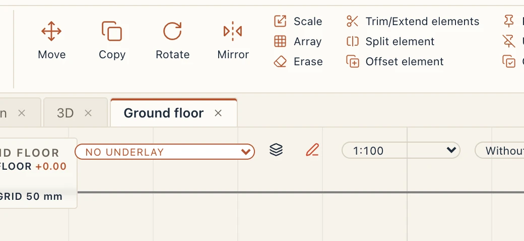
Rotate. The ribbon's Rotate (and Modify → Rotate) works with three clicks: the hinge, a reference point (where the thing points now: click on the edge you want to straighten) and a target point (where it must point). The selection turns in the preview as you move, the angle shows at the cursor, and snapping and polar tracking help you aim. The turn is the difference between the two directions, whatever the UCS. At any step you can type instead: an angle at the reference step is the turn itself (30), and an angle at the target step is the new direction, measured from the UCS's X axis. C turns a copy and leaves the original. Typing ROTATE (or RO) on the command line gives AutoCAD's: the base point, then the angle (typed, or a point measured from X), with [Reference/Copy]; R there is the same reference flow.
Every tool shows its letters in its tooltip; you can change them in View → Keyboard shortcuts… (see The interface and shortcuts). These are the ones used most:
| Model | Draft | ||
|---|---|---|---|
| Wall | WA | Line | L |
| Opening as a door, a window | DR, WN | Polyline | PL |
| Floor | SB | Rectangle, circle, arc | REC, C, A |
| Roof | RF | Move, copy | M, CO |
| Stair, room | ST, RM | Rotate, mirror, scale | RO, MI, SC |
| Column, beam | CL, BM | Offset, trim, extend | O, TR, EX |
| Section | SE | Fillet, chamfer | F, CHA |
| Measure | ME | Hatch, text | H, T |
| Fit everything | ZE | Erase | E |
Measuring
Measure (ME, the second quick tool, or MEASURE or DIST on the command line) measures without drawing anything: click points in a plan, a section or an elevation, snapping as you go, and press Enter. While you click, the live input shows each leg's length and angle; at the end the notice gives the total length, each leg (for one leg, its Δx, Δy and angle) and, from three points on, the area they enclose. In the 3D view the points snap to the model's corners, edges and faces; when they are at different heights the notice gives the true length in space, with Δz.
Snaps and helpers
Lapin snaps to the ends, middles and intersections of what is drawn, and to the grid. F3 turns snapping on or off, F8 ortho and F10 polar tracking. Their state shows at the bottom right of the view. Snaps take only what the view shows: an element its Visibility / Graphics hides (its category, a filter, a link, a phase) or that lies outside its view range draws nothing, so it offers no point to snap to, in plans, sections, elevations and 3D. With the modelling lines shown instead of the drawing (the pen button at the top of the plan), every line on the screen snaps.
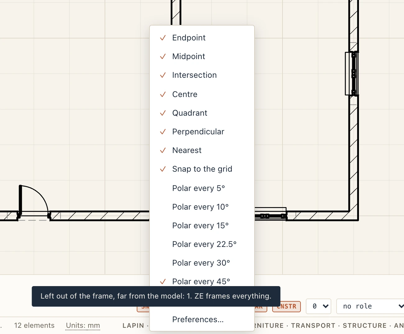
Which snaps. A right click on SNAP (or the ▾ beside it) lists the object snaps: Endpoint, Midpoint, Intersection, Centre, Quadrant, Perpendicular and Nearest, each on or off, then Snap to the grid and the polar tracking angle (every 5°, 10°, 15°, 22.5°, 30°, 45° or 90°). The same choices are in File → Preferences… → Grid and snaps, and they are kept for the next start.
The grid. The plan's grid is adaptive at first: its step follows the zoom. In Preferences → Grid and snaps choose Fixed and type its step (for example 100 mm or 1 m) and every how many lines one is drawn heavier. The grid then keeps that step at every zoom, and the cursor snaps to it where no object snap takes the point. Where the Nearest snap holds the cursor on a line or curve and the grid is on, the point slides along it to the nearest grid line, so one coordinate comes from the object and the other from the grid (no values like 1016.18). When the step is too fine for the zoom, only its heavier lines are drawn. The 3D view's ground grid takes the same step.
UCS. A user coordinate system, as in AutoCAD: type UCS on the command line, click its origin, then a point on its X axis (Enter keeps the angle). W goes back to the plan's own axes (World), B puts it on the project base point, S on the survey point with its axes east and north, and R turns it by an angle you type. The UCS chip beside SNAP shows when one is set, and its menu offers the same. In a UCS, typed coordinates (x,y, @dx,dy, d<angle), ortho, polar tracking and the grid follow its axes, and its icon (X red, Y green) stands at its origin. The UCS is kept in the project, and setting it is one undo step.
Selecting
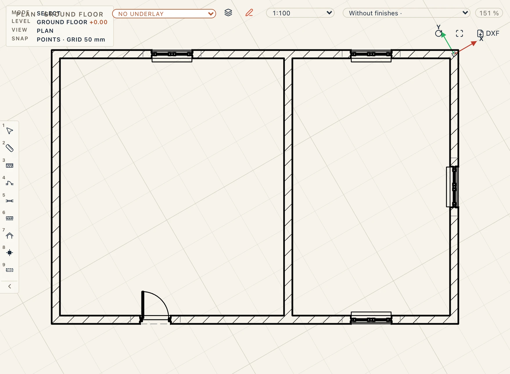
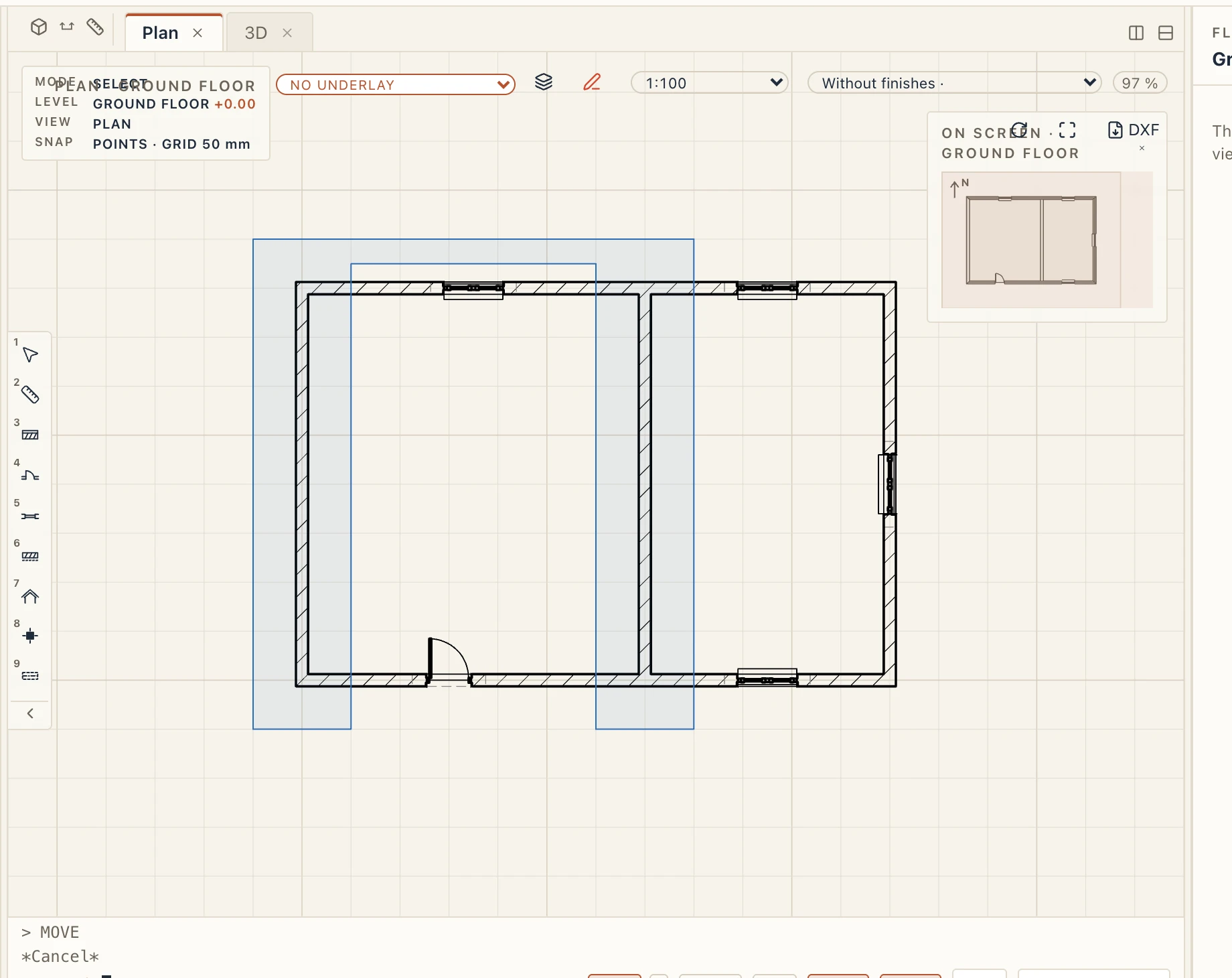
Click an element to select it; Shift-click adds to the selection. To select several at once, drag with the left button where nothing is selected. Dragged to the right, the box is blue and takes what lies wholly inside it (a window); dragged to the left, it is green and dashed and takes everything it touches (crossing), as in AutoCAD. Press Space while you drag and the box becomes a lasso that follows the mouse, keeping the mode the box had; Space again goes back to the box. On the command line, while a command asks you to select objects, type WP or CP and click the corners of a polygon, then Enter: a window polygon or a crossing polygon.
Copying and moving
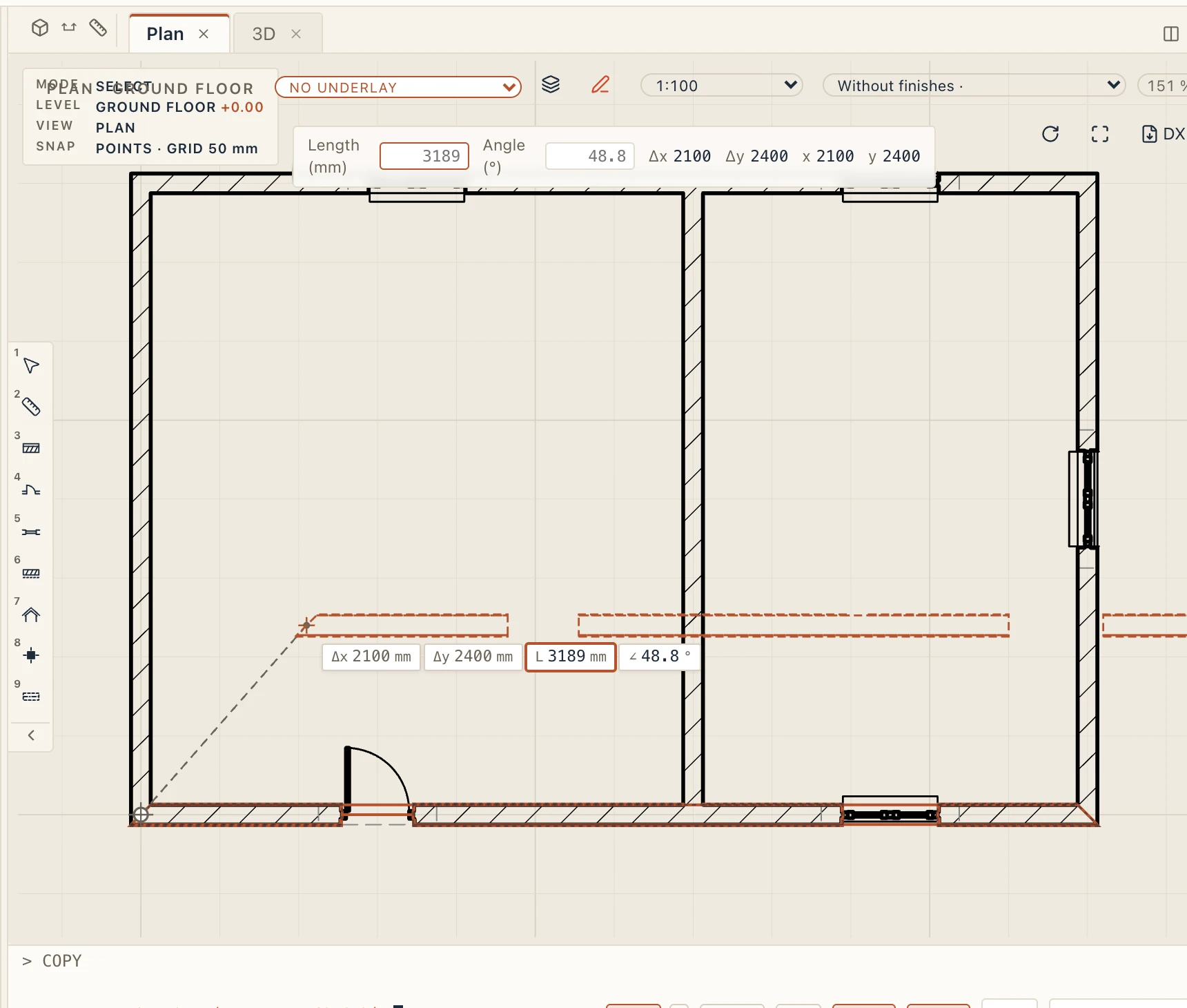
To copy, select the element and type CO. Click a base point, then a second point. Lapin keeps copying until you press Enter or Esc. Move (M) works the same way.
While you move or copy, a marker stays on the base point and a dashed line runs from it to the mouse, with a faded outline of what you move left where it was until you click or press Esc. The line and the marker change colour with the snap: green on a snapped point, blue when ortho or polar tracking holds the direction, the accent colour on a tracking line, grey when free. Next to the mouse, Lapin shows how far you have moved: Δx, Δy, the distance and the angle, in the project's units. You can type the distance and the angle there, as when you draw. In the Compact interface, these values are in the status line. Dragging a grip shows the same, and so does dragging a selected element itself, from the point where you pressed; press Esc before you let go and the element stays where it was.
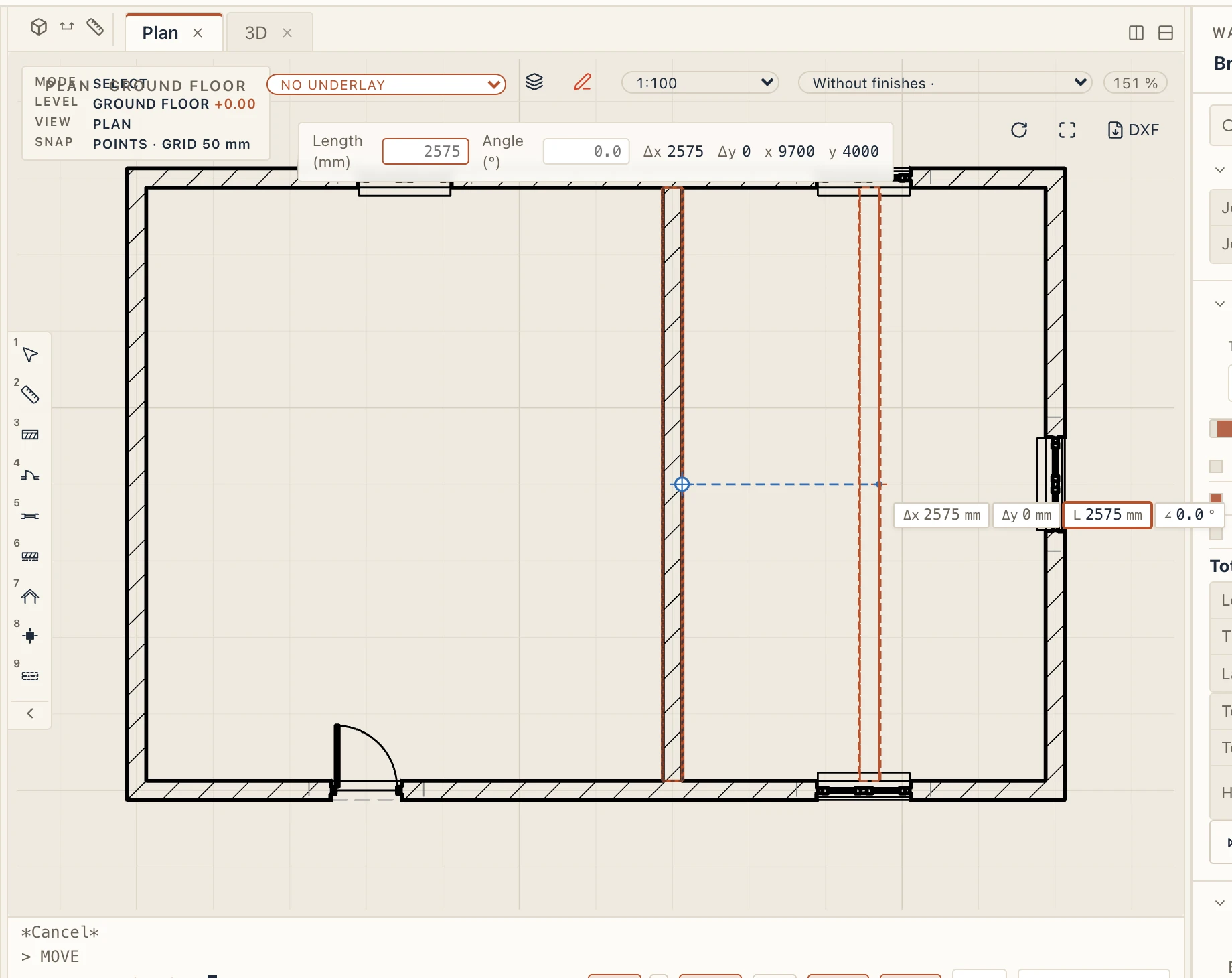
You can also drag instead. Drag the cross in the middle of a selected element to move it. Hold Ctrl (⌘ on a Mac) while you drag to leave a copy.
A door, a window or a wall opening moves and copies along its wall: only the part of the move along the wall counts, so typing 500 after the base point slides it 500 along the wall; moved into another wall, it goes into that wall. With its wall selected too, it goes with the wall.
A grid axis moves, copies, rotates and mirrors on its own, or together with other elements. A copy is a new axis of the same grid, named after the last axis that runs its way: with axes 1, 2 and 3, a copy of any of them is 4.
Array (Draft → Modify → Array, or ARRAY) copies drafted shapes, texts and symbols in a row, in a grid, round a centre or along a path, and keeps them an arrangement you change in their properties: see Arrays of drafting.
In sections and elevations
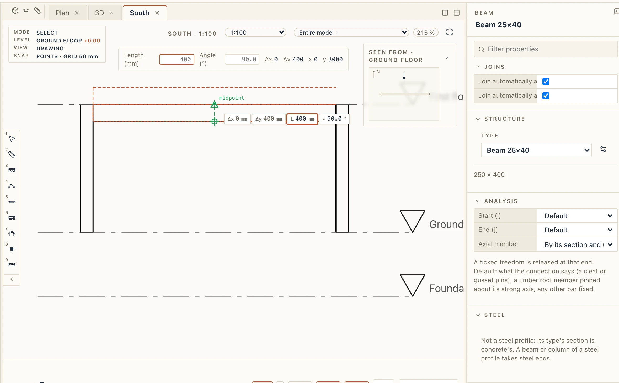
Move (M), Copy (CO) and dragging a selected element work in a section or an elevation too, in the view's plane. Along the view, the element moves in plan along the section's line; up or down, it rises or drops by its offset from its level (a wall's or column's base offset, a beam's top offset, a floor's offset). While you drag, its Offset from level in the properties follows. A door or a window still slides along its wall, and lines drafted on the view move in the view. Mirror there takes a vertical line and mirrors the elements across the plane through it, square to the view. Elements do not Rotate in a section or an elevation, as that would tip them over: turn them in a plan or in 3D. Drafted lines rotate and mirror any way. A pinned element stays where it is.
Pinning
Pin what must not move by mistake: an imported model, the grid, a survey drawing. Select it and choose Modify → Pin, or tick Pinned under Placement in its properties. A pinned element is not moved, rotated, mirrored, raised, sent to another storey or deleted, and it shows no grips. Its other fields still change: its type, height or material. It can still be copied, and the copy is not pinned. A wall joined to it that moves keeps the pinned wall's ends where they are. Pinning a group pins its members; a group with a pinned member does not move. Modify → Unpin (UP) lets it go again. Any element can be pinned: a wall, a reference from an imported file, a drafted line.
Elements. TRIM and EXTEND also take a wall clicked in a plan: trimmed at the walls that cross it, or carried on to the first wall ahead. OFFSET takes elements too: a wall, a beam or a strip footing (a parallel copy, by its axis or between its faces). Two command-line words work on elements: TRIMEXTEND (TE, Modify → Trim/Extend elements), which trims or extends walls, beams, strip footings, railings, MEP runs, paths and roads, floors, ceilings, roofs, drawn rooms, platforms and the parcel against a boundary you pick first, and SPLITELEMENT (SPLIT, Modify → Split element), which cuts one of them in two where you click (the parcel excepted). See Trimming, extending, splitting and offsetting walls.
Drafting
The Draft tab draws lines, polylines, rectangles, circles and arcs. It edits them with offset, trim, extend, fillet, chamfer and join, fills areas with hatches, and organises them on Layers. Import DXF brings a CAD drawing in as lines you can snap to and edit.

Ellipse (ELL) draws a true ellipse: its centre, the end of one semi-axis, then the other semi-axis (a point, or its length typed); the longer one is its major axis. Type A at the last step for an elliptical arc, then click its start and its end (anticlockwise). It stays an ellipse, laid within a millimetre like every curve, and snaps at its centre and its axes' four ends; its grips move it (centre), turn and stretch it (the major axis's ends) or set its other semi-axis. Trim cuts it into elliptical arcs, and a line meets it exactly (Trim by it, Extend to it). Offset gives a polyline, not an ellipse (the curve at a distance from an ellipse is no ellipse), laid within a millimetre of that curve; inwards by as much as its tightest bend it is refused. Extend carries an elliptical arc on round its ellipse, and Fillet joins a line and an ellipse with an arc touching both (a whole ellipse stays whole; Chamfer takes lines only). A DXF's ELLIPSE comes in as an ellipse, and a DXF export writes it back as an ELLIPSE, as it writes circles and arcs as CIRCLE and ARC. In Edit sketch elliptical arcs are not constrained yet. Convert to… makes a whole ellipse into an elliptical floor or ceiling.
Offset (O) copies a line, a polyline, a rectangle, a circle or an arc at a distance. Type the distance in the project's unit (in a project in millimetres 500 is half a metre; 2m or 1'6" say their own unit), click the shape, then the side it goes to; it asks for the next shape until you press Enter or Esc. Type T (Through) instead and each copy passes through the point you click. A polyline's corners stay sharp (mitred), as in CAD. Offset works in plans, sections, elevations, on reference planes and in the 3D view.
Explode (X, or EXPLODE) is the way back from Join: select polylines or rectangles and each becomes its lines, one for every side, on the same layer with the same pen and colour and in the same group, in one undo step. Circles, arcs, hatches and dimension strings are left as they are, and a selection with nothing to split says so. It works in plans, sections, elevations, on reference planes and on the work plane in the 3D view.
Every length the command line asks for is in the project's unit, and the prompt says which: Depth (mm), Height (ft-in). Angles, factors and counts are plain numbers: 90 after Rotate is 90° whatever the unit.
Tracing over a PDF or an image
File → Import PDF or image…, or Draft → PDF or image, brings a drawing in to trace over: a scanned plan, a photo of a facade, a PDF from another office. It goes into the plan, section or elevation in front, under its drawing.
- A PDF: choose the Page and the scale its drawing was made to (Drawn at 1:). A paper millimetre then measures that many millimetres here, so a 1:100 plan comes in at its true size. The page's lines come in as drafting you can snap to, edit and trace, and its pictures (a scan inside the PDF) as images under them. Either can be left out. The page comes in as one group named after the file, so Move, Rotate and Scale take it whole; double-click it to work on its parts.
- An image (PNG or JPEG): give its Width; its height follows its pixels. It need not be right: the next step sets it exactly.
Scaling to a known distance. With Then scale it to a known distance ticked (the default), the import goes straight on to scaling: the image or the PDF's group is selected, and you click two points on it a known distance apart, the two ends of a dimension or of the graphic scale. While you pick the second point, the box by the cursor shows how far apart they are now (↔); type their true distance there (2400, 50m, 3000+250; the project's unit unless you write one) and click, or press Enter. It grows or shrinks about the first point, and the whole PDF, lines and pictures, goes with it. Esc leaves it as it came in. Clicked without typing, the distance is asked for after. It is one undo step.
The same tool is there later, whenever you need it: Draft → Scale image, Scale to a known distance… on the right-click menu of a selected image or PDF, or the button of the same name in its properties.
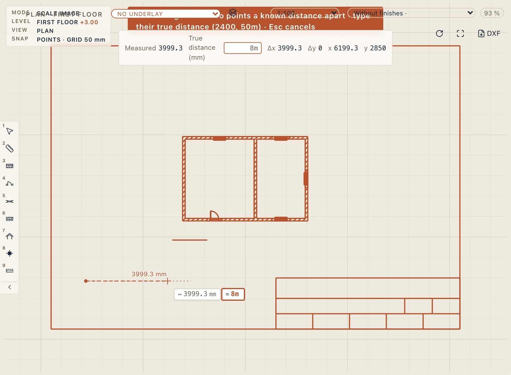
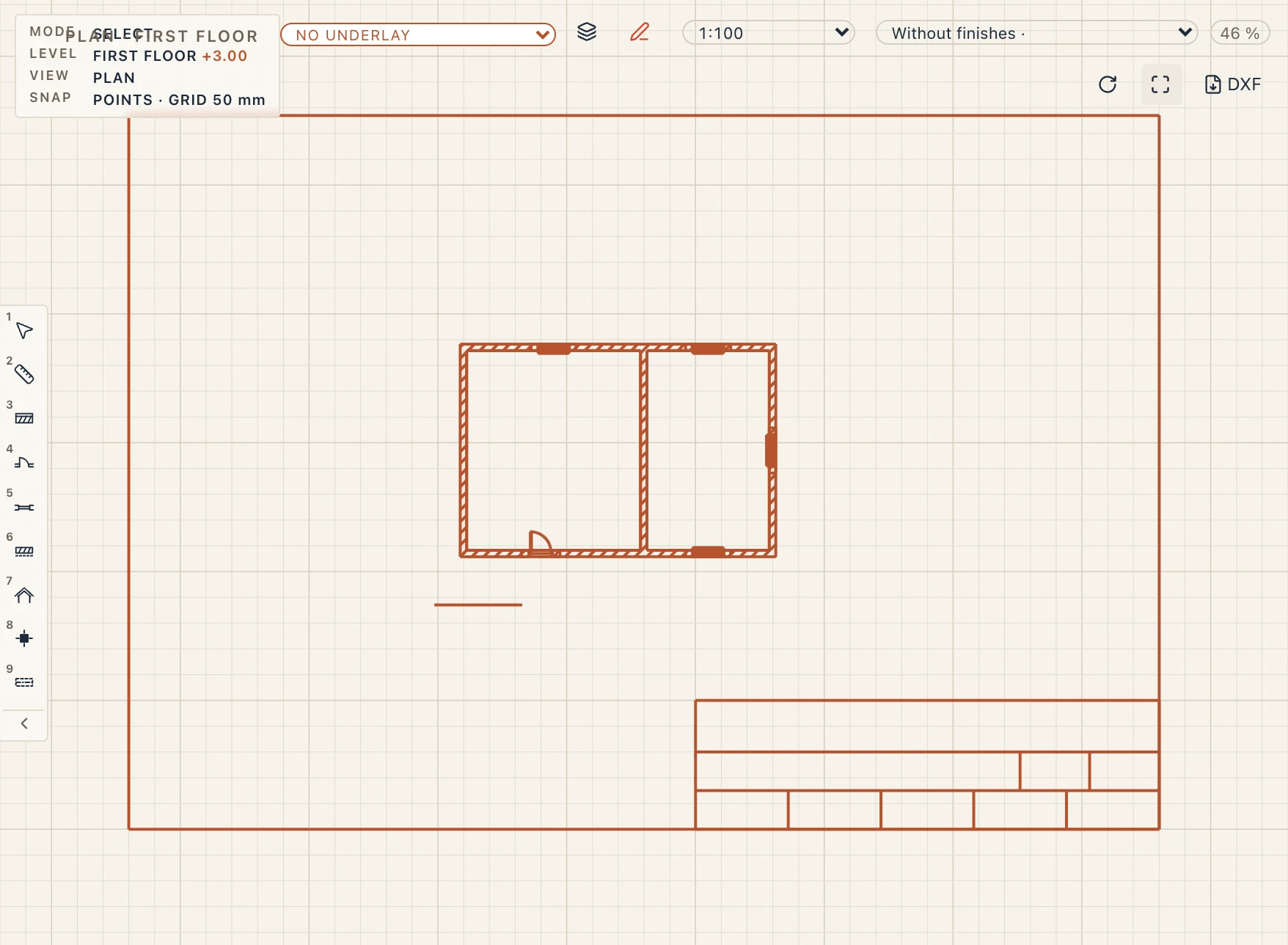
An image is see-through (its Opacity, 0.5 by default, in its properties) and is never part of the model: it does not print on sheets unless you leave it in the view.
Drafting in the 3D view
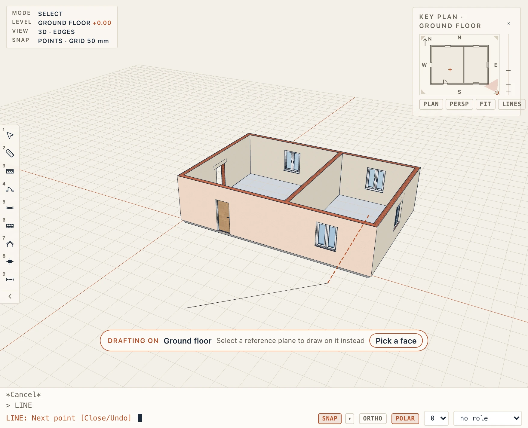
Line, Polyline, Rectangle, Circle, Arc and the Draft edits work in the 3D view too, with the command line at the bottom. While a command runs, the chip at the top says where you draw: on the active storey's level, or on the reference plane you selected. Pick a face in the chip, then a click on a face of the model, makes a reference plane on that face and draws on it. Points snap as on a plan: to the plan's cut lines (the walls' corners and faces) and to what is drafted on the same plane, with ortho and the tracking guides. What you draw is the same drafted element as one drawn on the plan, and shows there too.
Drafts in the 3D view
What you draft on a plan (lines, polylines, rectangles, circles, arcs) also stands in the 3D view, as lines at its storey's level (the level itself, not the plan's cut height); what you draft on a reference plane, a section or an elevation stands on that plane. Click one in 3D to select it, then move, copy, offset or delete it. View → Drafts in 3D, also in View → View settings of a 3D view, shows or hides them all; it is on unless you turn it off. Dimensions, texts, tags, hatches and construction lines (the role draft) stay on their views. A DXF brought onto a view lies in 3D too, on that view's plane, with a switch of its own (see Import and export).
Draw order
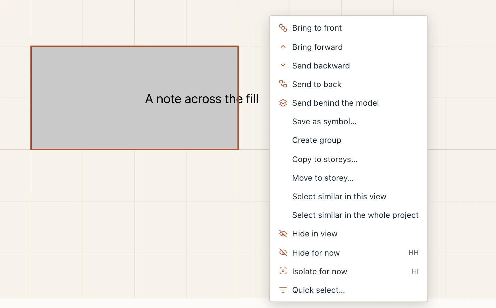
Where drafted elements overlap, the one drawn later lies on top. To change it, select them (lines, polylines, rectangles, circles, arcs, hatches and fills, texts, dimensions, tags, a DXF's shapes), right-click and choose Bring to front, Bring forward, Send backward or Send to back; Draft → Order and Annotate → Order have the same, with Ctrl+Shift+], Ctrl+], Ctrl+[ and Ctrl+Shift+[ (⌘ on a Mac). Forward and backward step past the next element the selection overlaps. Drafting draws over the model's own drawing; Send behind the model puts it under the walls' cut and the seen lines (a hatch under a wall), and a click there then takes the wall; Bring to front or Send to back bring it over the model again. On the command line, DRAWORDER (DRO) asks for the objects, then Above objects or Under objects (click the elements they go above or under, then Enter), Front, Back or behind Model. The order belongs to the view, is one step to undo, and sheets, the PDF and the DXF print it as you see it; what you draw afterwards comes on top.
Annotating
The Annotate tab has the dimensions, text, grid axes, levels and tags. A dimension reads the model, so it updates when a wall moves. How text, dimensions, axes and tags look is set in Manage → Drafting standards.
A Leader note (Annotate → Text) is a text with an arrow: click where the arrow points, then where the text goes, and type it. A Revision cloud (Draft → Fill, or REVCLOUD) draws a rectangle or a polygon as scallops; Revision cloud in the properties of a closed polyline or circle turns it into one or back. A Scale bar (Annotate → Sheets) is drawn at the view's scale. They work on every view and on sheets, where a legend of the views and live fields in texts join them (see Sheets).
The Dimension tool
Annotate → Dimension (DI, or type DIM) is one tool for every kind of dimension. It starts smart and takes the kind from what you click:
- Two points make an aligned dimension (or a linear one, horizontal or vertical, when the bar's second list says Linear), then the click for where its line goes.
- A drafted line clicked away from its ends and middle is measured end to end (a polyline's side too). Click a second line instead of the dimension line's place and you get the angle between them; the next click places its arc.
- A circle or an arc gets its radius, or its diameter or arc length when the bar's Arcs says so.
- A level's line clicked in a section or an elevation writes its spot elevation there (no Enter needed); Enter after the first point writes any point's level.
The bar under the view (the command line's) holds the rest. Its first list chooses a kind outright: Aligned, Linear, Angle, Radius, Diameter, Arc length, Ordinate, Slope, Level or Spot coordinate; each asks for its points in the command line, and the tool asks for the next one. The One by one / Chain / Baseline (from the first) list says how a dimension goes on after its first two points: one at a time, as a chain on one line (the old Continuous, also C), or as a baseline, where each next point is measured from the first one, as a dimension of its own on a line one step (7 mm on the paper) further out (B). Rooms and Exterior make the room and exterior dimensions, Add points and Remove points edit a string, Rules… opens the dimension rules. Typing a kind's first letters at the first point (AN angle, RA radius, LE level…) switches to it.

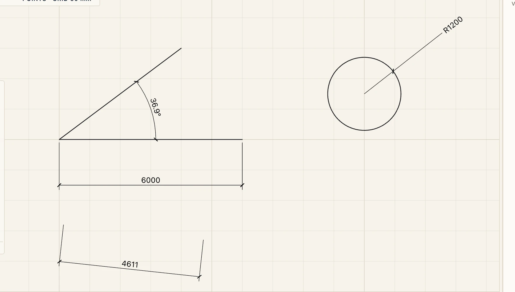
The old buttons are gone from the ribbon but still work: a quick slot, My tools, a shortcut or the letters of Linear, Angle, Radius, Diameter, Arc length, Slope, Ordinate and Spot coordinate start the Dimension tool at that kind, and Datum → Level (LL) starts it at Level. The typed commands (DIMALIGNED, DIMLINEAR, DIMANGULAR, DIMRADIUS…) are unchanged.
An aligned or linear dimension is a single one by default: click its two points, then where its line goes, and the command asks for the next. Esc leaves. Choose Chain in the command bar (or type C; it is remembered) and it goes on as a string instead: after the first two points and its line, each click adds the next point on the same line, with each segment's value shown as you draw. To finish the string, press Enter, right-click, click the bar's Finish string button, or click the last point again (a double-click does). U takes the last point back. Esc, another tool or another command keeps the string drawn so far and says so; undo removes it. A linear dimension keeps the direction it was given (horizontal or vertical, by which side of the two points you put the line) until you are clearly on the other side; Tab flips it, and the bar shows which it is. A string behaves like a polyline: a click selects all of it, and it moves, copies and deletes as one. A string that measures walls, edges or grid axes stays on them: dragged or moved on its own, only its dimension line slides, square to the string, so a slip of the mouse never leaves it measuring empty space; moved together with what it measures, it goes with them. Its grips sit on each measured point (drag to move it, Alt-click or Ctrl/⌘-click to take it out), in the middle of each segment (drag to move the dimension line through the point; Ctrl/⌘-drag to add a point where you drop it, Ctrl/⌘-click to add one halfway) and at the ends of the dimension line (drag to move the line; Ctrl/⌘-click to go on: the next clicks add points beyond that end, like continuing a chain in Revit, until Enter or Esc). To put more points into a string, as in ArchiCAD, select it and click Annotate → Add points (or type DIMADD, or Add points in its properties): each point you click goes into the string where it falls along its line, between the points around it or beyond an end as the new end, and holds on the wall, edge or axis it lands on; Enter or Esc finishes. To take points out, Ctrl/⌘-click their grips, or click Annotate → Remove points (DIMDEL, or Remove points in its properties) and click near each point; the segments either side become one. Each segment's value has a grip too: drag it to move the value off its place where segments are short and values would overlap; once it stands off its segment, a thin leader ties it back. Ctrl/⌘-click the grip, or Texts back on the line in the properties, puts it back. A moved value stays with its segment when points move, and turns with the string. Double-click a segment to type its value: the element it measures moves, and so does everything after it in the string. The properties show each segment's value and text, split a string into single dimensions, and join single dimensions that continue one another on one line. A right-click on selected dimensions offers the same: Split into single dimensions, and with several selected Join selected dimensions and Align selected dimensions, which puts each string parallel to the first one on the first one's dimension line (the others are left as they are), in one undo step.
Annotations on a plan (dimensions, texts, drafted lines, tags) can go to another plan where they are, since plans share their coordinates: select them and choose the plan in their properties, under View to move them or Copy to to copy them. This also brings dimensions made on a site plan to the level's floor plan. A dimension's points then hold on what the new plan cuts at that place: walls, edges, axes.
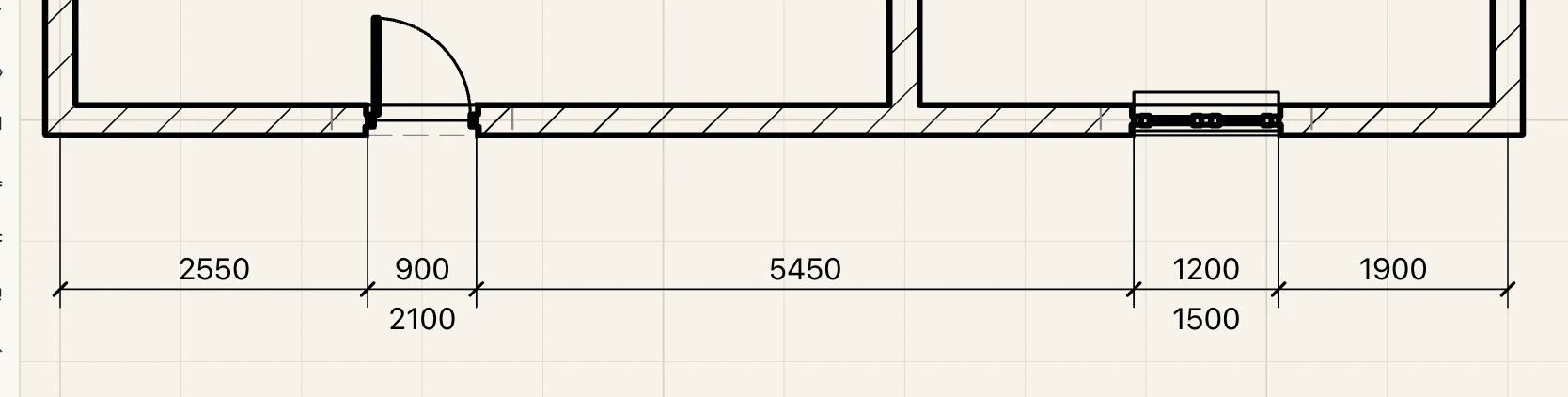
Opening heights. A segment of a dimension string that goes from one jamb of a door, window or bare opening to the other writes the width over the line and the opening's height under it, as Romanian and European drawings do. It is read from the model each time, so it follows the opening when it is resized, moved or given another type; a segment you typed a text over writes none. Manage → Drafting standards → Dimensions → Opening height sets it for each dimension style: off, 150, h=150, h=150 with the sill p=90 under it, or 150/90, in the style's unit. It works in plans, sections and elevations, and sheets, the PDF and the DXF print it. New projects have it on (the height alone); a project made before keeps its dimensions as they were until you turn it on there.

Trailing zeros. A dimension with three decimals writes 2.500 and 3.000. Tick Manage → Drafting standards → Project → Suppress trailing zeros and every dimension drops them instead: 2.5 and 3, as CAD programs do. Each dimension style can also choose for itself in its Trailing zeros column, next to Decimals: as the project (the default), keep (2.500) or suppress (2.5). It applies to the values of linear, aligned, radius, diameter, arc-length and ordinate dimensions and to the opening heights under them, on screen, on sheets and in the PDF and the DXF; feet and inches, written in fractions, have none to drop. It is off until you turn it on, so existing drawings keep their look.
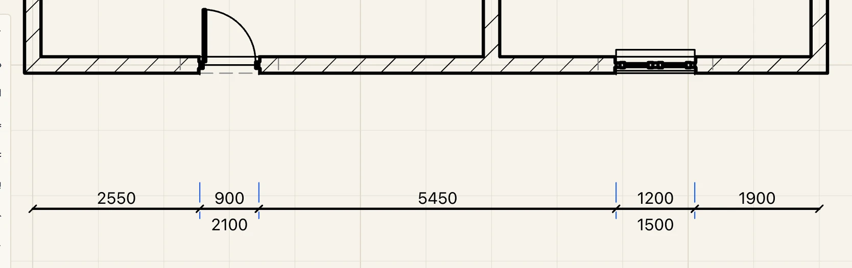
Extension lines and the dimension line. As in AutoCAD's dimension styles, each style in Manage → Drafting standards → Dimensions says how its extension lines and its dimension line are drawn. Extension lines off leaves out a string's first extension line, its last (second off) or both, where a wall's face or another dimension already shows the point; a dimension can choose for itself in its properties, under Extension lines off (as the style when empty, or all shown to bring them back on a style that leaves them out). Fixed extension mm gives every extension line one length on the paper, measured back from the dimension line towards the point, so a string far from the wall does not draw long lines across the plan; a point nearer its line than that keeps its line from the gap, as before, and empty means from the gap. Extension pen mm, Extension colour and Extension line, and Dimension line pen mm, Dimension line colour and Dimension line, give each its own pen, colour and line type (a dashed extension line, a heavier dimension line); the arrows and ticks take the dimension line's colour, the values keep the style's. Empty, they draw as before: a 0.13 mm pen, the style's colour, continuous, so existing drawings keep their look. They apply to linear, aligned, angular and arc-length dimensions; the engine draws them, so the plan, sheets, the PDF and the DXF show them alike, and a saved standards file carries them.

Levels. Levels are written in metres with two decimals: +3.00, −0.15, ±0.00. Manage → Drafting standards → Project sets how many with Level decimals (0 to 4: +3, +3.0, +3.00, +3.000, +3.0000) and whether they drop their trailing zeros with Level trailing zeros: as the project (the default, so they follow Suppress trailing zeros), keep (+3.150) or suppress (+3.15). With three decimals a level reads +3.150, suppressed +3.15, and a whole +3.000 becomes +3. It applies wherever a drawing prints a level: the level marks across sections and elevations (Lapin's own and a level symbol of yours, its {level.elevation}), spot levels ({point.elevation}), level dimensions, the base and survey points and the terrain's levels. A level dimension placed by a script can carry its own (decimals, zeros). In an imperial project levels stay in feet and inches.
Dimensions on a line. A dimension point clicked on a grid axis or on a wall's centre line holds on the line, not on a point of it. Drag the axis's end along itself to make its head fit the view, or make the wall longer or shorter: the dimension keeps measuring where you put it and its line does not turn. If the axis or the wall moves across, the point goes with it, at the same place along. A dimension on a wall's face likewise stays where it measured when the wall is stretched along itself. Dimensions made before attach to a grid axis the same way; one on a wall's centre line is attached anew by clicking its point again.
What a dimension follows. A dimension's point clicked on an element holds on it, and follows it when the element is moved, turned or edited: a wall's face or centre line, a door's, window's or opening's jamb, a grid axis, a column, and what the plan does not cut: a stair's outline (its sides, its flights' and its landing's edges), a beam seen overhead, a floor's or a ceiling's edge, a piece of furniture, a railing, a Studio solid seen below. The point is kept in the element's own frame, so a stair moved or turned takes the dimensions on its corners with it, and made wider, the dimension on its side follows the side. A point on nothing, or on a drafted line, stays where it was clicked. Dimensions made before on a turned stair, column or piece of furniture follow it from the moment the project opens.
Exterior dimensions and dimension rules
Annotate → Exterior dimensions (ED, or type EXTDIM) dimensions the outside of the building on a plan at once. Each straight exterior facade gets parallel dimension strings outside it, one beside the other, in the order set by the dimension rules, starting at the wall. The points hold on the walls, like any dimension's.
- With walls selected, only their facades are dimensioned. With nothing selected, every exterior wall of the plan's level is.
- Asked on a site plan, the strings go to the level's floor plan instead.
- Run it again and the strings it made on the plan are replaced, not doubled. Strings you drew yourself are kept.
Annotate → Dimension rules… opens the settings of Exterior dimensions and of Room dimensions, in two tabs. They belong to the project and travel with the drafting standards (Manage → Drafting standards, with the options). Each string has a tick and ↑ ↓ buttons to put the strings in order: for the exterior from the wall outward, for rooms from the side inward.
| String | What it measures |
|---|---|
| Details | every feature on the facade: corners and the openings' jambs |
| Openings | from the facade's start to each door's and window's centre, and to its end |
| Axes | from the start to each grid axis crossing the facade, and to the end |
| Rooms | the thicknesses of the walls meeting the facade from inside, and the distances between them |
| Overall | the whole facade |
Room dimensions have only Details (the side, with the openings' jambs) and Overall (the side's whole length). Besides the strings:
- Offset is the distance in millimetres on the paper from the wall's face (or the room's side) to the first string, and Spacing the distance between strings.
- Dimension style is one of the project's dimension styles; the default style when empty.
- Measure to (exterior only) says what corners and partitions are measured to: the walls' faces, their core's faces or their axes.
- Skip openings narrower than leaves out the openings under that width, in metres.
- Reset to defaults brings the dialog back to the built-in rules; nothing changes until OK, which is one undo step.
Automatic text placement. Where segments are short, a 10 cm reveal next to a 2.40 m window, the value does not fit between its witness lines. Lapin moves it for you: just outside its segment on the free side (the end of the string, or a neighbour wide enough to keep its own value), and where both sides are taken, a row above the line or under it, in turn, so close values are staggered. A value never goes over another value or across another dimension line of the view, so the strings of an exterior dimension, or of a room's, keep clear of one another. Moved further than a set distance, it gets a thin leader back to its segment. Values that fit stay exactly where they always were, and a value you dragged by its grip keeps its own place (Texts back on the line hands it back to the automatic placement). The setting is under Text placement at the bottom of Annotate → Dimension rules…: Automatic text placement (on in every project, new or old) and Leader when moved beyond, in millimetres on the paper (5 by default). Each dimension style can choose for itself in Manage → Drafting standards → Dimensions: Text placement as the project, on or off, and Leader beyond mm (empty: as the project). The engine places the values, so the screen, sheets, the PDF and the DXF show them alike; they count in paper millimetres, so the same string at 1:50 needs fewer moves than at 1:100.
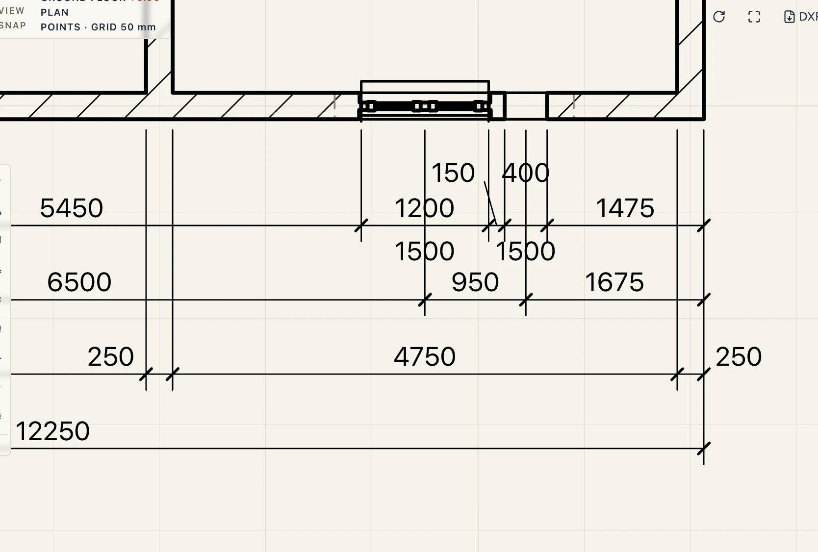
Tags
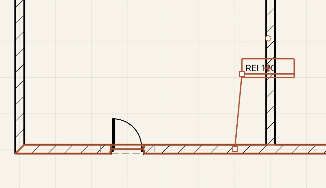
Annotate → Tag (TG) puts a box on a view with what an element says of itself, and a leader to it. It is one tool for every kind of tag: the first list of the bar under the view says what it tags.
- Element: the mark, name, class or type, Fire rating, Acoustic rating, Thermal transmittance, or Another parameter… by its name; or a tag type of the drafting standards. ALL DOORS & WINDOWS tags every door and window of the plan at once (as Annotate → Door & window tags).
- Room: click inside a room for its name, number, area, function, height or floor finish. ROOM STAMPS… opens what every room's stamp shows (the same as Room tag…).
- Parameter: type the parameter's name in the bar (Fire rating,
Pset_WallCommon.FireRating). Annotate → Tag a parameter, off the ribbon now, still starts the tool here. - Material / layers: a build-up tag type; TAG TYPES… opens their editor.
- Keynote: the element's classification code (or its title), see Classifications.
LEADER turns the leader on or off. Click the element, then where the tag goes (type E first to bend the leader at an elbow). Typed at the element's prompt, ELEMENT, ROOM, PARAMETER, MATERIAL and KEYNOTE choose the source too.


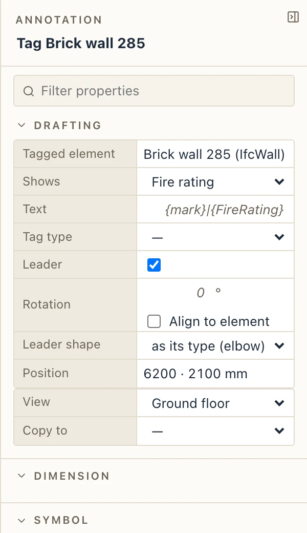
A tag reads any parameter: the element's own, its type's (then every element of the type shows it), a standard property such as Pset_WallCommon.FireRating, or one an imported element came with. A name is found without its spaces, so Fire rating and FireRating are the same. To fill one in, use Parameters in the element's or its type's properties: type a name (Fire rating, Sound rating, Moisture resistance and Thermal resistance are offered), or choose Add a standard property… for the IFC properties of its class. The tag follows as soon as there is a value, and lengths are written in the project's units.
A selected tag has grips. Drag the box to move the tag: the leader keeps pointing where it did. A tag goes with its element: when the element is moved, turned, mirrored or reshaped by its grips, its tag follows it, keeping its place beside it, and the leader stays on it; a tag you moved keeps the offset you gave it. Drag the leader's middle to bend it at an elbow (Ctrl/⌘-click the elbow to straighten it again), and its end to point it at another spot (Ctrl/⌘-click: back on the element's middle). The properties change what the tag Shows, give it a Text of its own ({mark}|{FireRating} writes two lines), a Tag type, or turn the Leader off. The engine draws tags, so sheets and PDFs print them as you see them. The tag types in Manage → Drafting standards → Tags read the same fields in their templates; a new project has Fire rating, Acoustic rating and Thermal transmittance among them.
Leaders as ArchiCAD's labels. By default a tag's leader is an elbow: an oblique line from the element to a knee, then a shoulder that runs under the text and underlines its first row, with no box round the text. After you click the element, the next click is the knee and the text goes beside it. Drag the knee's grip: the oblique line keeps to 30°, 45°, 60° or 90° from its end (hold Shift for any angle), and dragged past the end the text moves to that side, aligned towards the knee. Drag the text to move it with its knee. In Manage → Drafting standards → Tags, Leader… on a tag type (and the build-up editor) sets its Leader shape (an elbow, or straight from a box), what the shoulder underlines (Underline: the first row, each row, the last row, or nothing, when it stops at the text's side) and Extension mm, how much further the shoulder reaches from the text, beside the engine's preview. With a leader per layer, each ends under its own row, their knees one column; dragging the knee moves the column. Leader shape in a tag's properties overrides its type's; a tag whose leader was bent at a free elbow keeps its straight leader. Tags in projects made before keep their straight leader in a box.
A door's or window's marker is edited part by part, each text moved or turned and each end of its line drawn out: see Doors and windows.
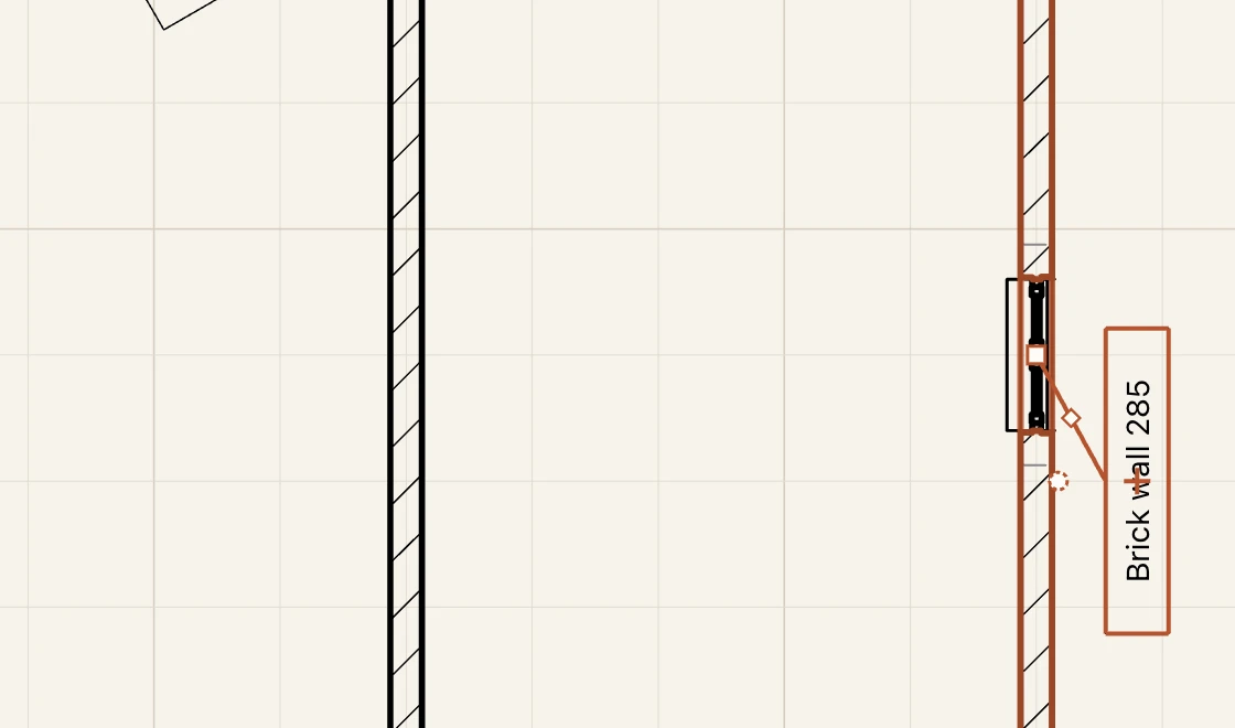
Turning a tag. In a tag's properties, Rotation turns its text and its shoulder or box by an angle in degrees from level, and Align to element makes it follow the direction of the element it tags (a wall's or beam's axis, the longest edge of anything else), turning with it when the element turns; the rotation is then added to that direction. A tag is always drawn upright, never upside down. A selected tag has a turning grip over its text: drag it in steps of 15° (45° and 90° among them; hold Shift for any angle), and Ctrl/⌘-click puts the text level again. The leader still reaches the element. Plain and build-up tags turn alike, in plans, sections and elevations, and sheets, the PDF and the DXF print them as you see them.
What a tag tags. While the Tag tool waits for an element, the one under the cursor is highlighted in the accent colour; hover a placed tag, or select it, and the element it tags is highlighted.
Other elements' fields. A tag's text may read beyond its element, with a scope before a dot: {storey.code} (its storey's parameter), {project.number}, {host.FireRating} (a door's wall), {room.name}, a door's {fromRoom.number} and {toRoom.number}, and the project's own parameters by their key alone. A field may be a formula too: {= upper(storey.code) & "." & number}, {= area * 1.1 | 0.00}. The Shows list in a tag's properties groups them by where they come from (its storey, the project, its host, its room). See Parameters worked out by formulas.
A tag drawn by a symbol
A tag type, or the room stamp, can be a drawing of your own instead of a text. Draw the tag as a symbol (Manage → Symbols…): its lines, boxes and circles as it should look, and a text wherever a value goes, each holding fields as a template does — for a room, {storey.code}.{Hall}.{Flat}.{number} in one box, {name} beside it, {area} and {Floor finish} under them. The Fields list of the symbol editor offers the tagged element's fields and your storeys' parameters. Then, in Manage → Drafting standards → Tags, choose the symbol beside the tag type (Text only is the plain text), or in Room tag…, Drawn as. Every tag of that type, every room's stamp, is drawn as the symbol at its point, its texts filled from its element; they follow the element and what it reads (a storey's code changed changes every stamp). A tag still has its leader, drawn from the symbol's box; the symbol's own fields ({view.scale}, {attr.…}) keep working. A symbol deleted leaves the type's text.
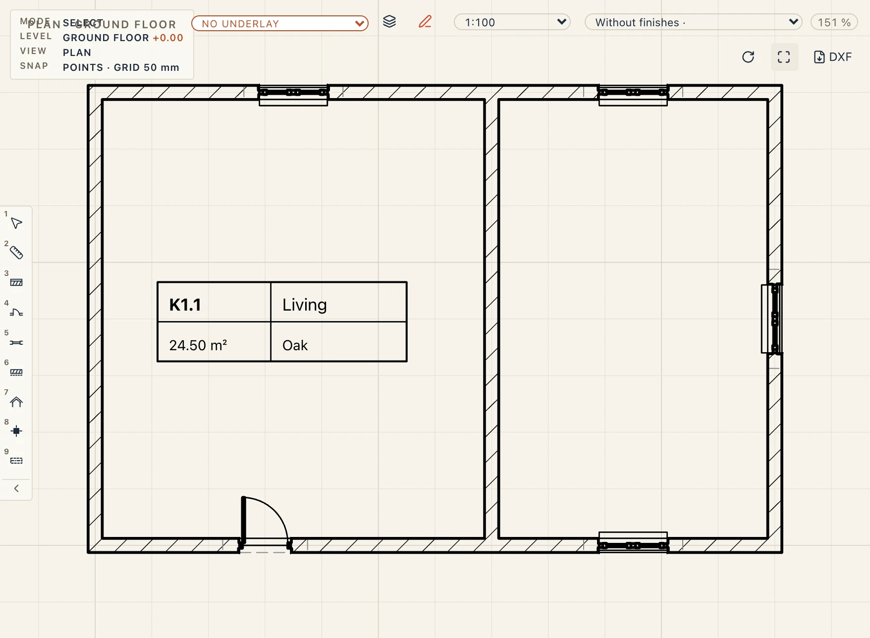
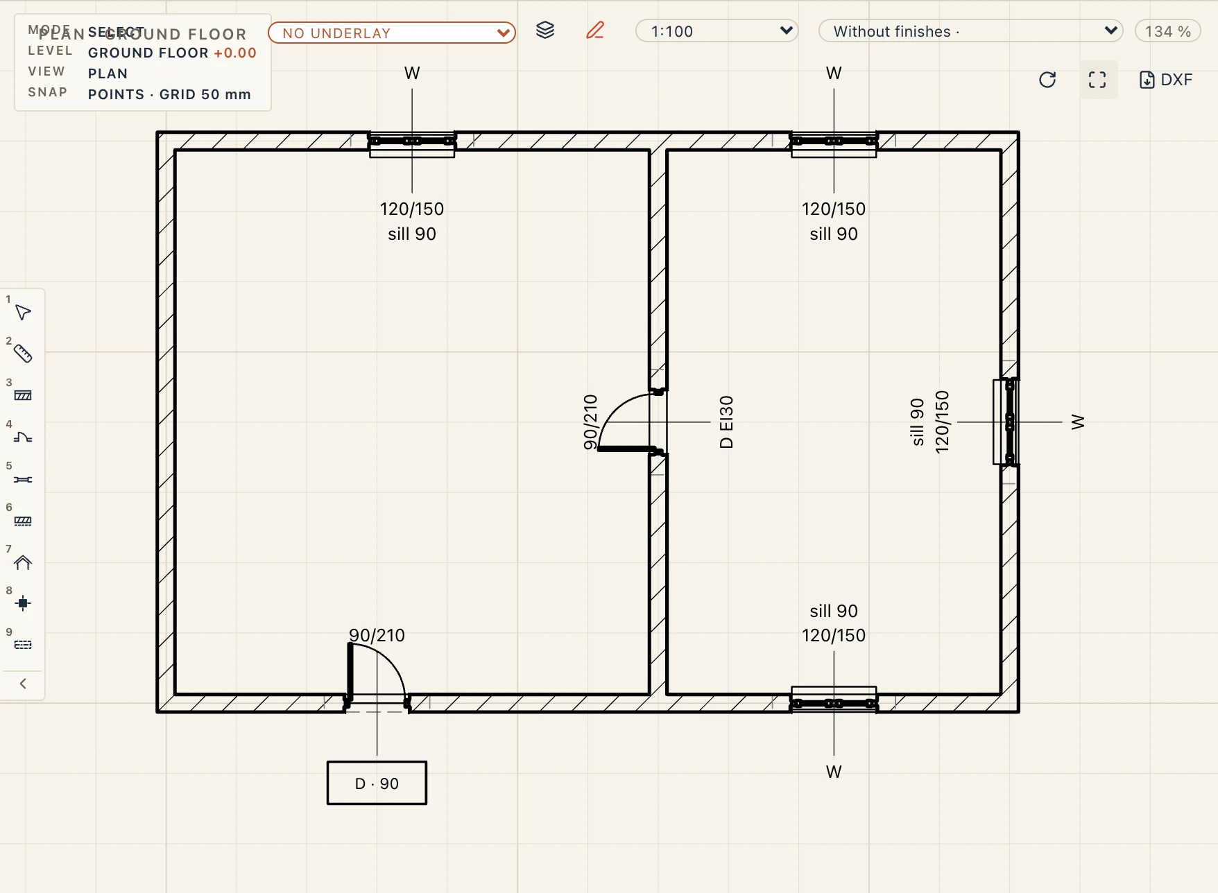
A door's or window's marker (Annotate → Door & window tags) can be drawn by a symbol too: choose it beside the marker's type (Door marker, Window marker). The marker keeps its line across the wall and its inner text (width/height, the sill), and the symbol stands beyond the line's exterior end instead of the outer text, turned as the texts lie (along the wall, or along the line). Its texts read the door or window: {mark}, {width}, {height} and {sill} as the marker writes them (in the type's unit), any parameter, formulas. In the plan the symbol has the outer text's grips: drag it to move it, turn it by its grip; Ctrl/⌘-click puts it back. Without a symbol the marker is drawn as before.
Tag rules
Under the tag types, Tag rules chooses a tag's type by what its element is. A rule has a Class (IfcDoor, IfcWindow, IfcSpace…), a Condition and the Tag type it gives. The condition is a formula over the element's fields, as {= …} reads them, written bare or in braces: width > 1.2 (a door's or window's width, height and sill in metres), FireRating != "", IsExternal, storey.code == "P". It holds when it is true (a number other than 0, a text not empty). For each class the rules are tried in their order and the first that holds wins; the arrows move a rule up or down among its class's, the bin removes it, New rule adds one. A rule that holds gives its type to every tag of the element's class over the one the tag was made with, door and window markers and room stamps included, on every drawing, so a door made wider takes the wide door's marker. With no rule, or none that holds, each tag keeps its own type. A tag type removed takes its rules with it. The rules travel with the standards (Export standards…, a .lapinstandards file, where each rule is an entry of the import preview) and in the project.

A tag can still have its own type: choose a Tag type in its properties (a marker's among the marker types) and the rules leave it so; By the rules gives it back to them. Untick Shown to switch one tag off: it prints nowhere (sheets, PDF, DXF) and stays on screen as a faint outline, so you can select it and switch it on again.
Build-up tag
A build-up tag writes an element's layers as an architectural note: a header (EXTERIOR), a line for each layer, a footer (INTERIOR). A new project has Build-up (exterior → interior): each line is the material's description (its name when it has none), its λ when it has one, and the layer's thickness in mm. Choose it in the Tag tool's bar and click a wall, a floor, a roof or a room's finish; other elements get the field instead. The text is read from the model each time it is drawn: change a layer, a material's description or its λ, and the tag follows.
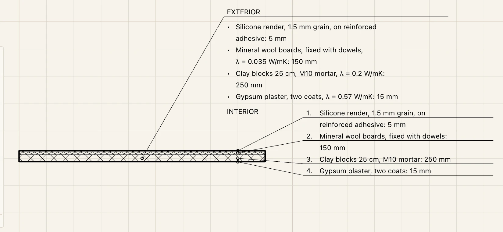
Its form is set in Manage → Drafting standards → Tags: make a tag type's Shape build-up, or click Build-up… on one, to edit it beside a preview on one of the project's wall or floor types.
- Header text and Footer: written above and under the layers (empty: none;
|starts a new line). - Each layer: the line written once per layer. It reads the layer's fields,
{description},{material},{thickness}(in the unit chosen under Thickness in),{note}(the layer's note in its type),{function}(core, finish, insulation…) and{index}; any parameter of the material by its name or its symbol,{λ},{μ},{ρ},{Reaction to fire}(see the material's Data); and the element's,{name},{type},{mark}. Insert a field… puts one where the cursor is and lists the parameters the project's materials have. - Square brackets make a part optional:
[, λ = {λ} W/mK]is written only where the material has a λ; a part is left out whole when a field in it is empty. [ ] makes the selection such a part. To write a bracket itself, type\[or\]. - Order: from the exterior to the interior of a wall (its first layer's side is its exterior, so a flipped wall still starts there), from the top to the bottom of a floor or a roof; or the other way. Choose the order that runs as the layers lie beside the note, so leaders per layer never cross.
- Layers of no thickness (membranes, foils, paint) are written unless you untick shown. A layer that changes material up its height writes a line for each material.
- Leaders: one, to the element, or one per layer, each from its line to a point inside its own layer, where the view can tell the layers apart (a wall in plans and sections, a floor in sections; elsewhere the tag keeps one). Drag the leader's end along the element to cross it elsewhere.
- Lines start with a bullet, a dash, their number or nothing; they wrap at Width mm on paper, hanging after the bullet, and a value stays with its symbol and unit (
λ = 0.035 W/mK).

Like any tag, a build-up tag follows its element, and sheets and PDFs print it as you see it, λ, μ and ρ included. A Text of its own in its properties replaces the line per layer for that tag alone.
Tables
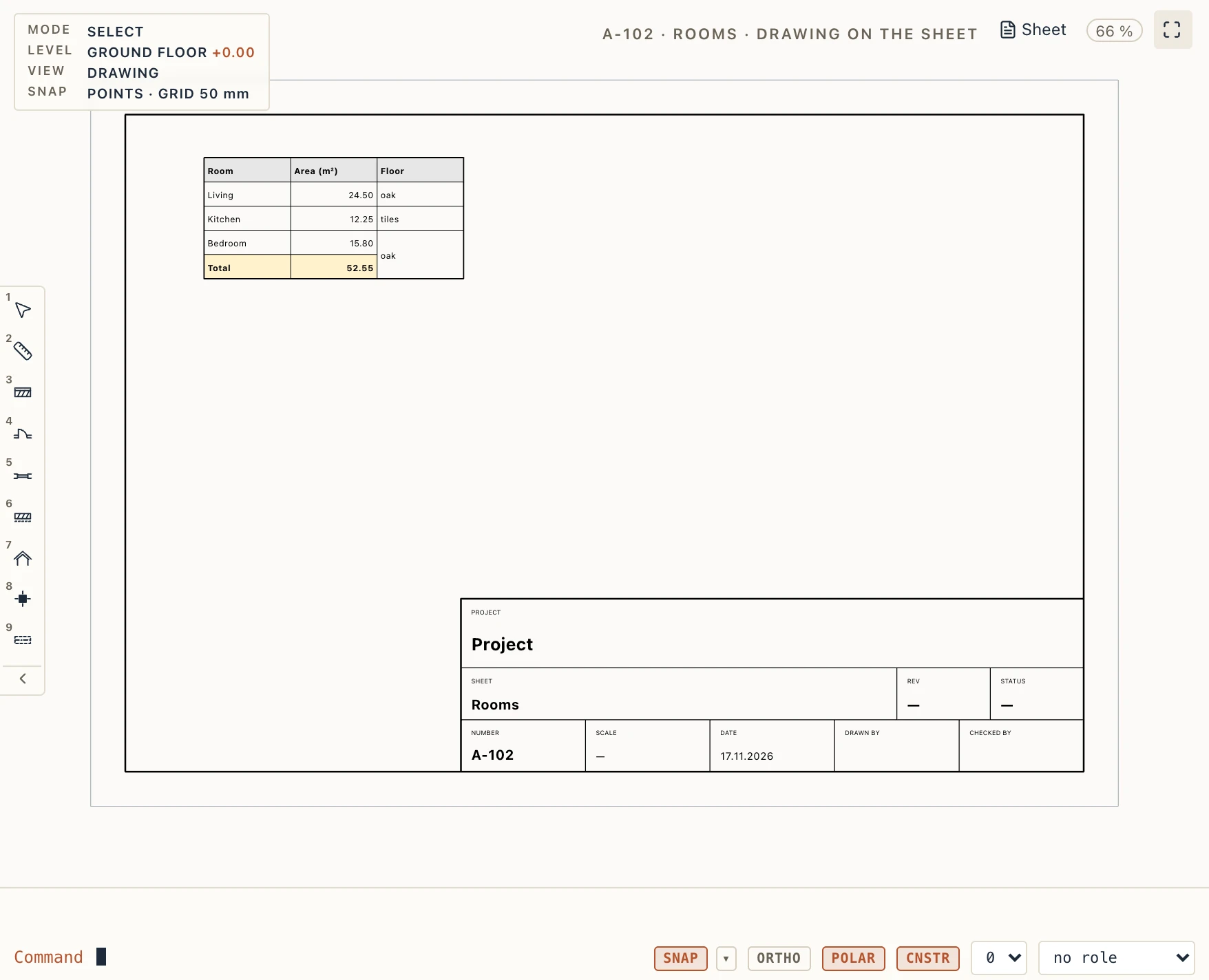
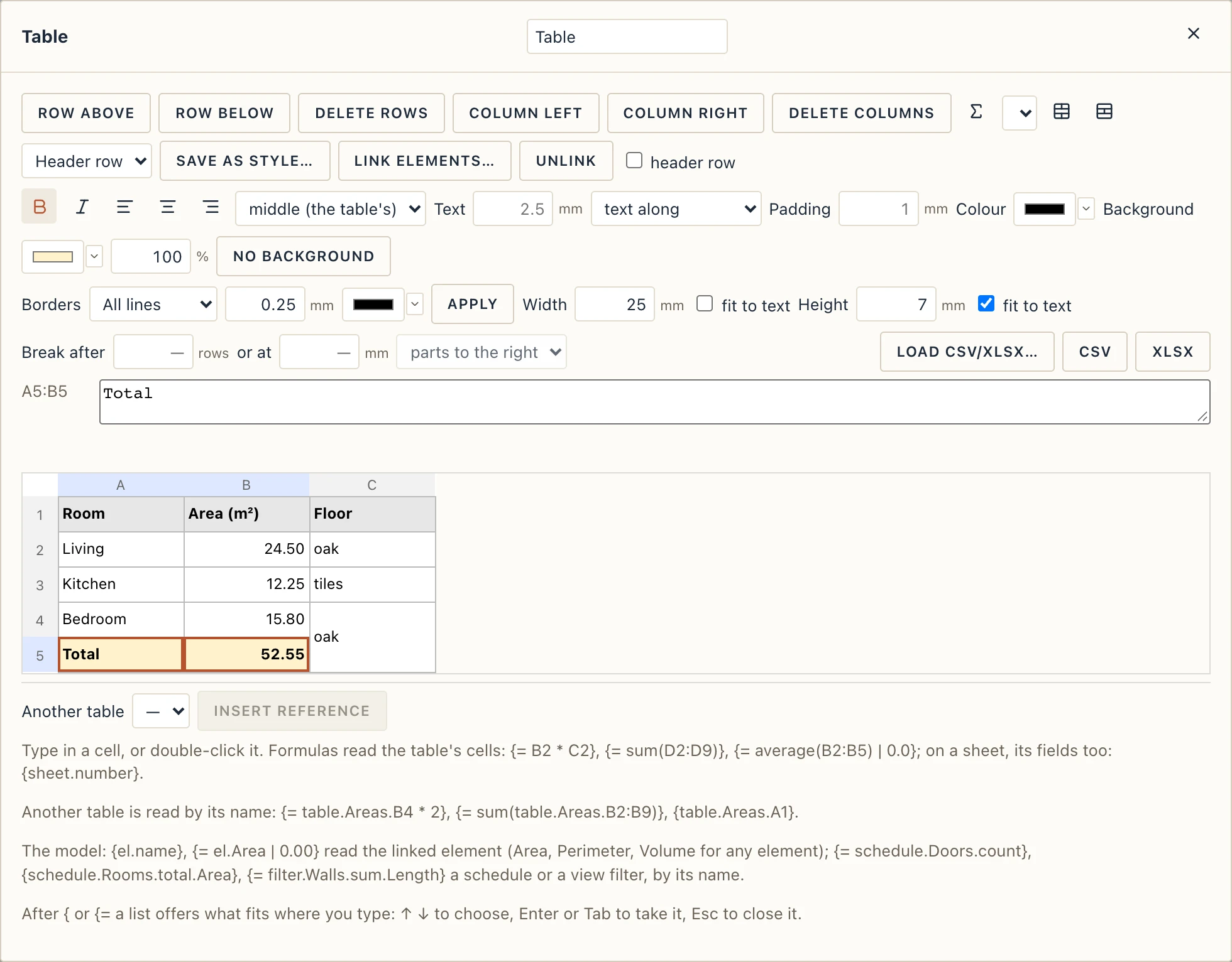
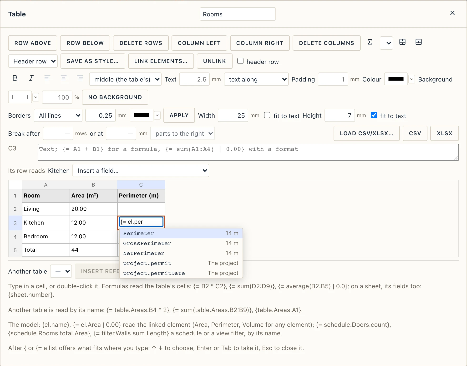
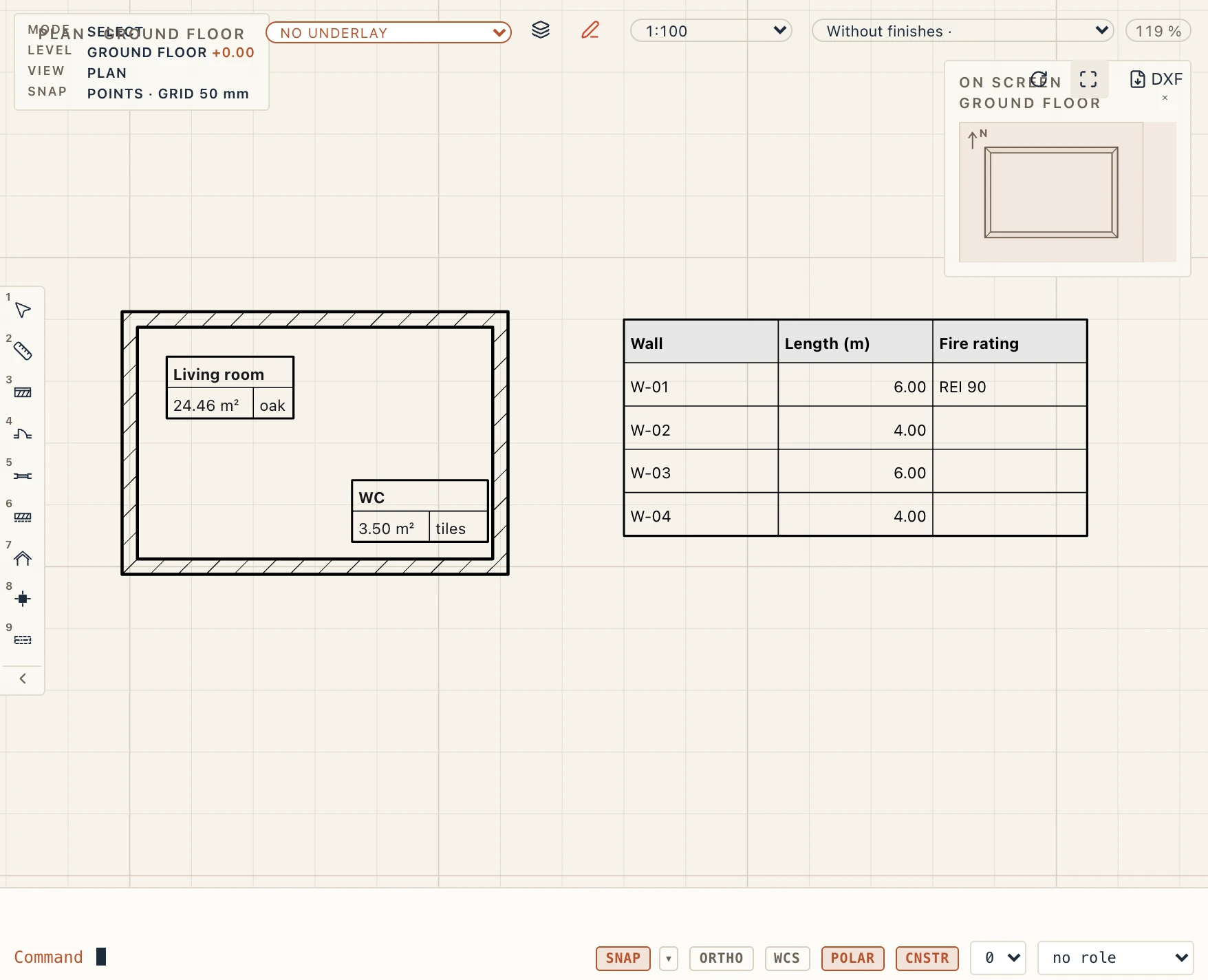
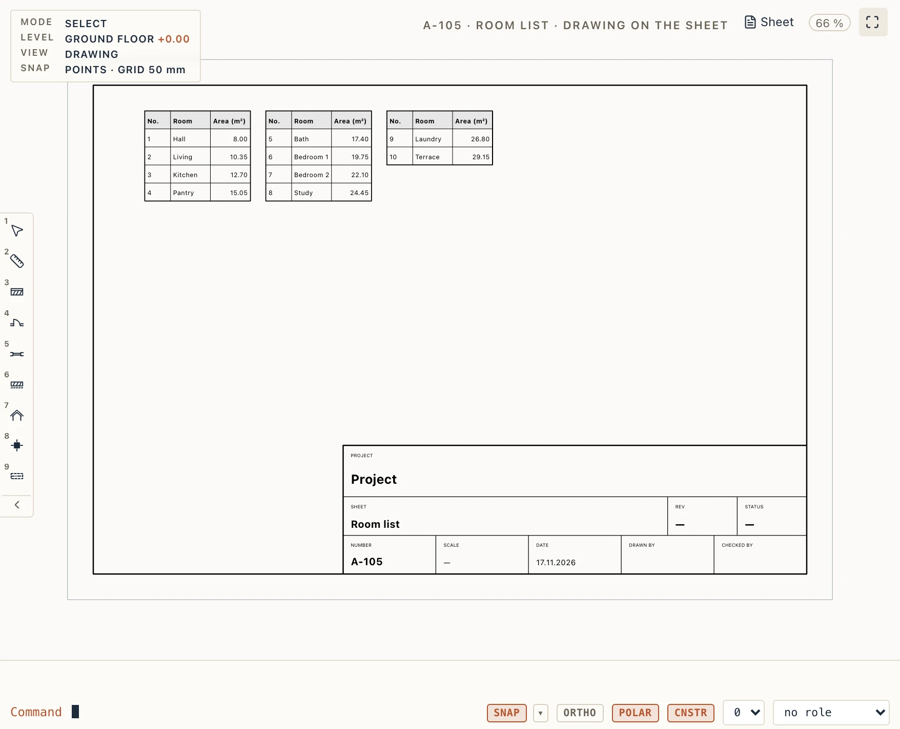
Annotate → Table (TT) puts a table of your own on a plan, a section, a drafting view or a sheet's paper: set its rows, columns and look in the command bar (Header row, Grid lines, Minimal, No lines), then click where its top-left corner goes. Its editor opens; double-click the table, or Edit table… in its properties, to open it again.
- Cells hold text, on several lines (Shift+Enter in a cell). Type in a cell, or double-click it; Enter keeps the text and goes down, Tab goes right, Esc leaves it as it was. Cells copied from a spreadsheet paste as they are.
- Formulas are written as in a title block,
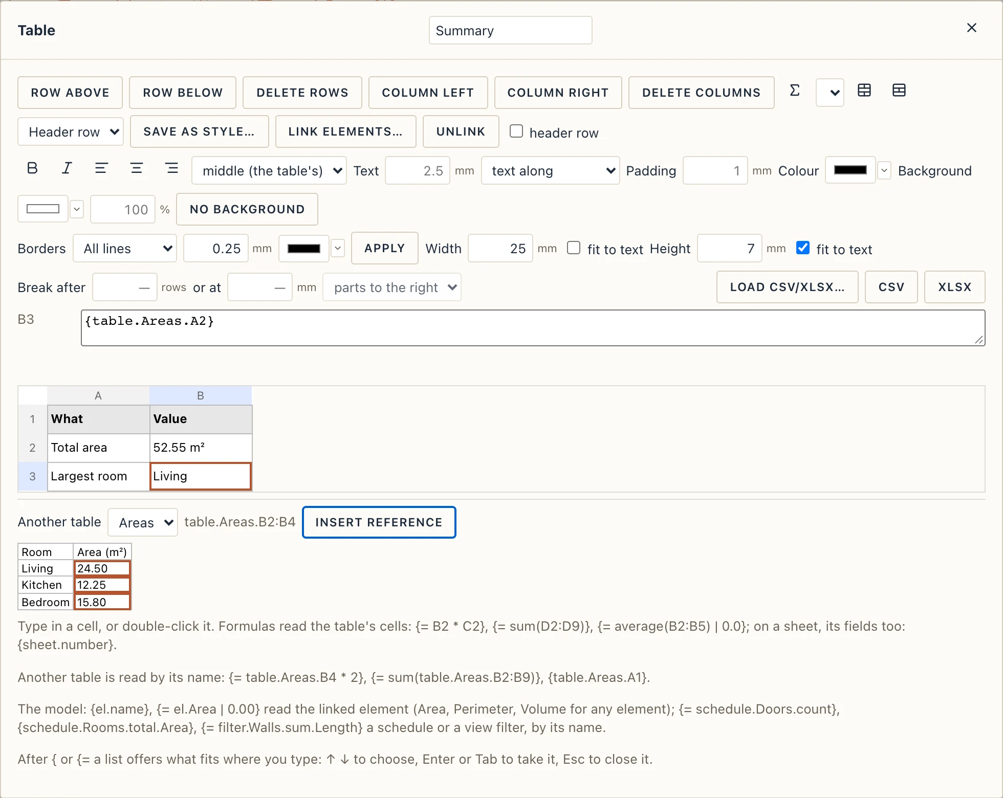
{= …}, and read the table's cells by their address:{= B2 * C2},{= sum(D2:D9)},{= average(B2:B5) | 0.0}(a format after the bar),{= count(A2:A20)}. A text cell that starts with a number counts as that number. Put a row or a column in, or take one out, and the formulas follow, as a spreadsheet's do; a formula that reads its own cell, or a cell taken out, shows<…>and the editor says why. On a sheet a cell reads the sheet's fields too:{sheet.number},{project.name}. - Other tables. Give a table a name of one word in its editor (Areas, at the top), and any table reads its cells by that name:
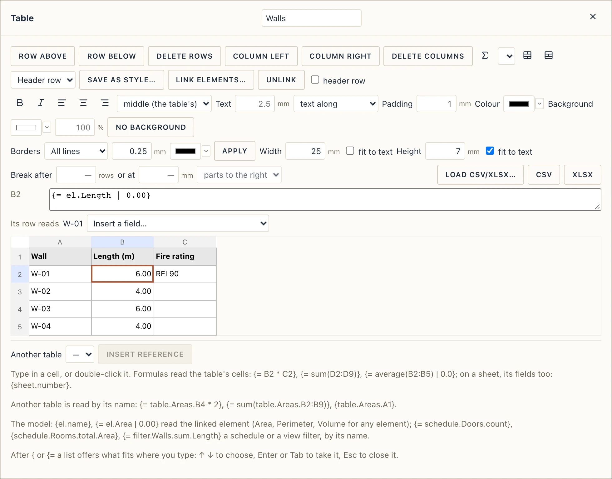
{= table.Areas.B4 * 2},{= sum(table.Areas.B2:B9)}, or{table.Areas.A1}to show a cell as it reads. Another table, under the grid, shows the other tables: click a cell (shift-click for a range) and Insert reference puts it into the selected cell where the cursor was in the bar, inside a formula as it is, elsewhere as a field or as a total. A name is looked for on the same sheet first, so a sheet duplicated with its tables reads its own. Rename a table and what reads it follows; delete it and what read it showsREF; rows and columns put into it or taken out move the references other tables make to it, as in a spreadsheet. A formula that comes back to its own cell through another table shows<…>, and both tables say why. - From the model. Link elements… hides the editor behind a bar: select elements in any view, then link them To the selected cells, A row each (from the first selected row: rows are added as needed and the first row's texts are copied down, so a row written once lists them all) or to The whole table; Unlink takes the links off. A linked cell reads its element by
el.:{el.name},{el.FireRating},{el.storey.name}show a field as a tag writes it,{= el.Area * 1.1 | 0.00}reads it as a number (m², m, m³), with every field a schedule can list. Measures read by their common names on any element: Area, NetArea, GrossArea, Perimeter, Volume, Weight are a room's net floor area, perimeter and volume, a wall's net side area, a slab's net area, a door's or a window's area, as its quantities name them ({el.NetFloorArea},{el.NetSideArea}read those too). Insert a field… under the bar lists the element's fields with their values now, its quantities and their common names among them. A cell also reads a schedule by its name,{= schedule.Doors.count},{schedule.Rooms.total.Area}(its totals line),{= schedule.Rooms.sum.Area}(oraverage,min,max),{schedule.Rooms.B3}(a cell as printed, row 1 its headings), and a view filter of Visibility / Graphics,{= filter.BearingWalls.count},{= filter.BearingWalls.sum.Length | 0.0}; write a name that has spaces without them ("Bearing walls":BearingWalls). Nothing is copied: the table reads the model every time it is drawn, so it follows every change. If a linked element is deleted, its cells show<el.…>and the editor says so; undo brings the value back. - Suggestions while typing. After
{or{=, in a cell or in the bar above the grid, a list offers what fits where you type: the functions with how they are called (round(x; decimals),if(condition; then; else),sum(A1:A9; …)), thenel.and the linked element's fields with their values,schedule.and the project's schedules, thencount,total.,sum.… and their columns,filter.and the view filters,table.and the other tables with their cells as they read. Typing narrows it; ↑ ↓ choose, Enter or Tab takes the one marked, Esc closes the list. The engine makes the list, so what it offers reads. A half-typed formula is not marked wrong at every key: the cell's errors show once you stop typing for a moment, or when you keep its text. - AutoSum. Σ (or Alt+=, as in a spreadsheet) with one empty cell selected writes
{= sum(…)}of the numbers right above it, up to a header row, an empty cell or a text, else of those right left of it; with several cells selected, it puts a total under each of their columns in the first empty row below them, adding a row when there is none. The list beside Σ does the same with Average, Count, Min or Max. A total follows the rows: rows put in right above it, or linked A row each later, are added in, since the rows a link adds go in above the first row that holds a text of its own (the total) rather than over it. One undo step. - Merge the selected cells (the first one's text stays), or split them again; insert rows above or below and columns left or right, or delete the selected ones.
- Widths and heights are in paper millimetres, so a table reads the same at any scale. A row fits its text by default, never shorter than its height; tick fit to text for columns as wide as their widest text (wrapped text stays in a column of its own width).
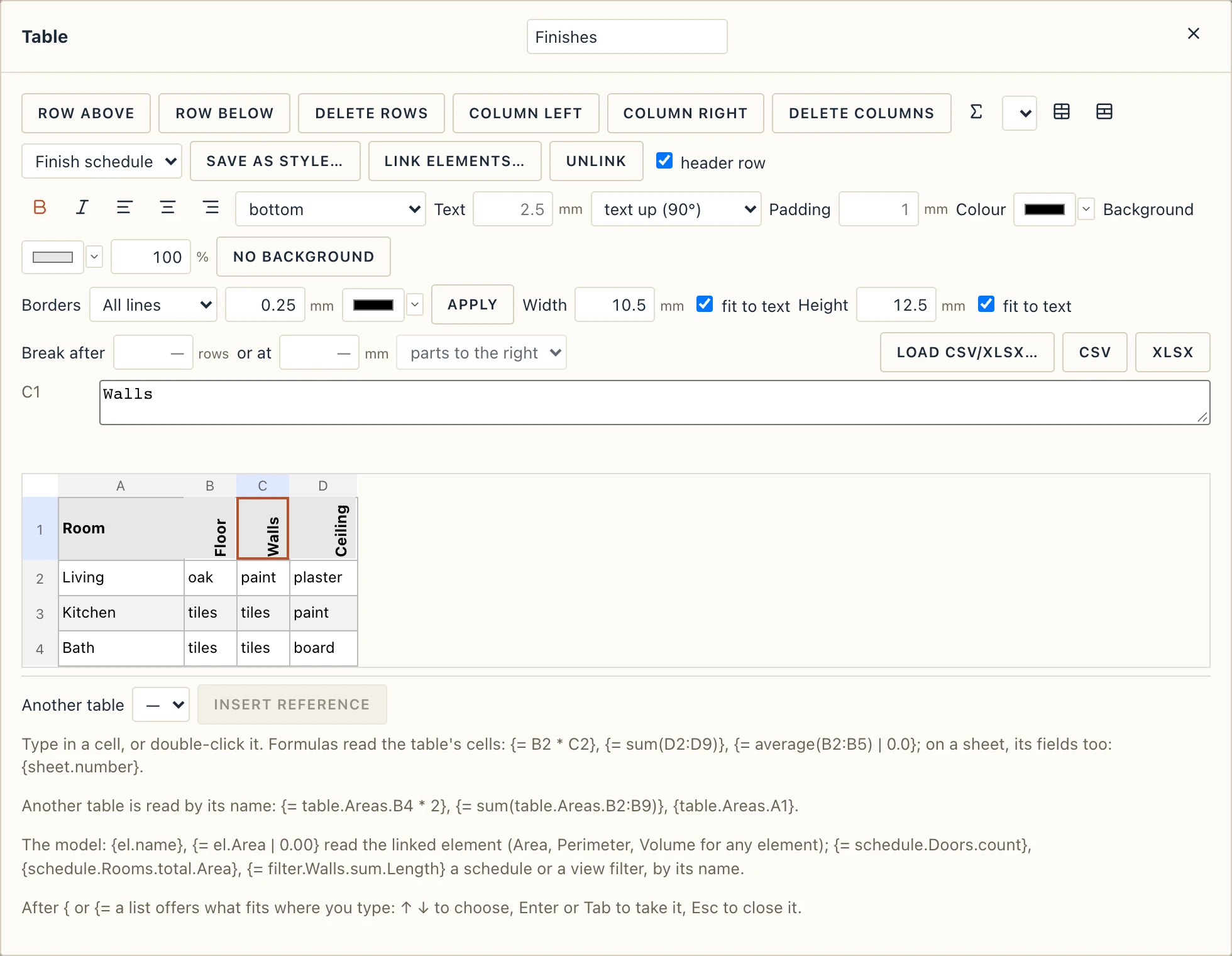
- Turned text and padding. Text up (90°) or text down (270°) turns the selected cells' text to read along the row's height, and a row that fits its text grows to its length (a column heading over narrow columns); in a row of a height of its own the text wraps at it. Padding sets the space round a cell's text (empty: the table's).
- Table styles. Save as style… keeps the table's look in the project's drafting standards: its lines, its cells' colours, alignment and turns, its columns' widths and rows' heights and its header rows (tick header row for the selected rows). Asked to keep its cells too, the style is a template: a new table made in it starts as a copy. Your styles are offered beside the built-in looks when you make a table and in the editor's list, where choosing one restyles a table (its texts and widths stay). Manage → Drafting standards → Tables renames or removes them, and a standards file (Export…, Import…) carries them to other projects. The built-in looks stay as they were.
- Long tables. Break after a number of rows, or at a height on paper, and the table goes on in parts beside it (parts to the right or parts below), each with the header rows again (tick header row for the rows it repeats); a merged cell is never cut in two. Place a part… puts a part on another sheet or view: click where its top-left corner goes. It reads the table as it is now, moves with the Modify tools, and deleted it comes back beside the table.
- CSV and Excel. Load CSV/XLSX… brings the cells of a CSV file or of a workbook's first sheet into the table from the selected cell on, adding rows and columns as needed, in one undo step; CSV and XLSX save the cells as they read.
- Grips. Select a table in the view: the grips along its top edge set its columns' widths, those along its left edge its rows' heights (a row given a height stops fitting its text).
- Bold, italic, alignment, text height, text colour, background and its opacity apply to the selected cells; Borders draws all lines, the outside, the inside, one side or none, at a width and in a colour.
Each change is one undo step. The engine draws the table, so the view, the sheet, its PDF and its DXF show the same thing; it moves, copies and turns with the Modify tools.
Grid axes
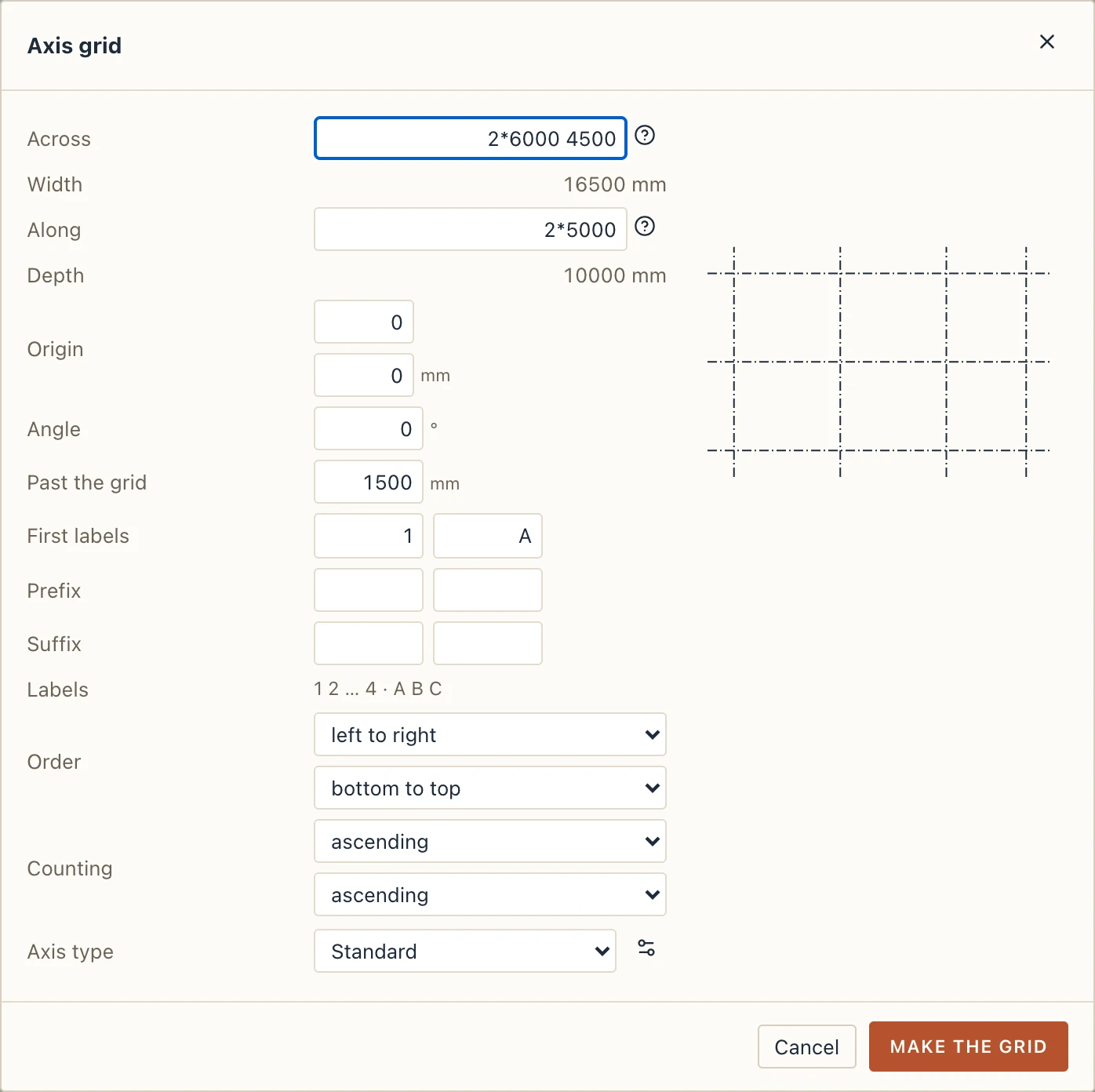
Annotate → Grid axis (GR) draws one axis by its two ends; it takes the next label of its direction. Annotate → Axis grid… lays a whole grid at once: the spacings Across (the numbered axes, left to right) and Along (the lettered axes, bottom to top) in the project's units, as 6000 6000 4500 or 3*6000; the Origin where the first axes cross, an Angle, how far the axes run Past the grid, the First labels, their Order (the numbered axes left to right or right to left, the lettered ones bottom to top or top to bottom) and Counting (ascending from the first label, or descending from it: choosing descending turns a first label of 1 or A into the one that ends the family on it, 4 for four axes), and the Axis type. With replace the grid's axes ticked, the axes drawn so far go.
Typing the spacings. Spans are separated by spaces: each makes the next axis at that distance. N*span stands for N equal spans, and the two mix in one field: 100 2*300 200 is 100, 300, 300 and 200. A span takes a comma or a dot for its decimals (5,4 or 5.4) and may name its own unit (6m, 20'). A span that does not read is named under the fields (Not a length: 2*abc), and the grid waits until it does. Hover the ? beside a field for the same in short.
Labels. The axes count on from the First labels: a number at the end counts up (1, 2… 10; A1, A2), letters at the end run through the alphabet (A… Z, AA; a, b), and any other label takes a 1 after it (A- gives A-1). Prefix and Suffix put text of your own before and after each label of one family, never counted: a prefix X- across gives X-1, X-2…, a suffix ' along gives A', B'…. Each family has its own. Labels shows the ones the axes will take.
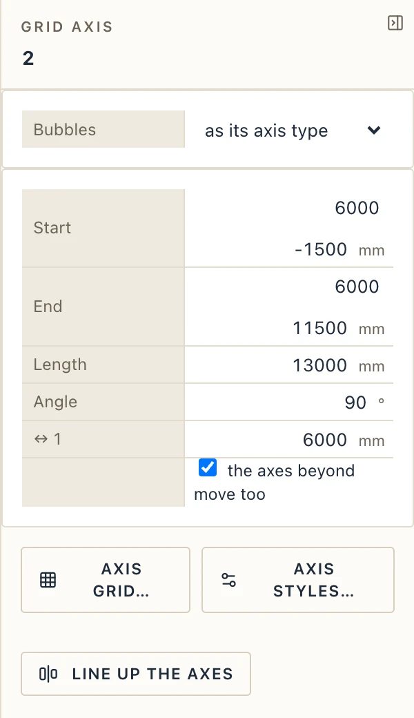
Click an axis to select it. Its properties show its Start and End, Length, Angle, and its spacing from the parallel axis before it (↔). Type a new spacing and the axis moves; the axes beyond it move too, unless you untick the axes beyond move too. Bubbles chooses which ends carry a bubble. Axis styles… opens Drafting standards → Grid axes, where the bubble, its size, the line type and the first label are set. Select the whole grid to list its axes and their spacings.
Temporary dimensions. A selected axis shows, in the plan, its distances to the parallel axes on either side, as a door's or a window's temporary dimensions do. They stand near the point where you clicked the axis (kept within the stretch it shares with its neighbours), so on a long axis they are where you work; selected from the project browser, they stand at the middle of that stretch. Click a value and type a new distance (in the project's units; sums like 3000+150 too), then Enter: the selected axis moves so the dimension reads it, the other axis stays, and dimensions held on the axes follow, in one undo step; Esc leaves it as it was. With move the axes beyond too ticked, beside the dimensions (the same tick as in its properties), the axes past it, on the far side from the axis you measured to, move with it, so their spacings stay. The padlock makes the distance a dimension of the plan, held on both axes. An axis of a radial grid, whose axes start from one centre, shows the angles to its neighbours instead; type an angle in degrees and the axis turns about the centre.
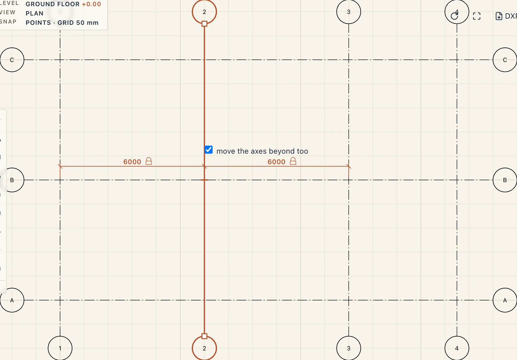
Line up the axes makes the parallel axes start and end on the same lines, taking the axis selected as the reference: with several axes selected, only those line up with it; with one, all the grid's axes that run parallel to it.
Renumber axes… (in Annotate, beside Axis grid…, in an axis's or the grid's properties, or RENUMBER… in the axis tool's bar) labels the axes again in order across them, however they were drawn: the axes running up the plan from left to right, or those running across it from bottom to top, or only the axes selected (Ctrl/⌘-click several). Order runs them the other way when you want it: right to left, or top to bottom. Choose numbers or letters (leave out I and O is ticked, so H is followed by J), the Start (1, 01, 101, A…) and an optional Prefix (S1, S2…). Counting descending counts the labels down from the Start (10, 9, 8…; E, D, C…); left empty, they end on 1 or A. A start too low for the axes (2 for four axes) is refused. An axis whose new label another axis keeps is refused, so start after it or give a prefix. Dimensions on the axes keep measuring them, under their new labels, and so does an axis renamed by hand in its properties. It is one undo step.
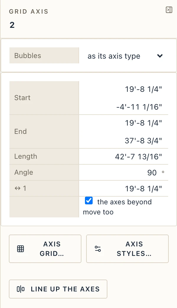
Every length here follows the project's units. In feet and inches, the ends and spacings read 19'-8 1/4", and the levels are written in feet and inches too.

Symbols
A symbol is a small drawing you reuse: a pile mark, a north arrow, a revision cloud's tag, a fire door's key. It is made of lines, polylines, rectangles, circles, arcs, fills, hatches and texts, and each copy placed in a view is one element that you can move, turn, flip, copy and delete. Change the symbol and every copy follows.
A symbol has a scale. An annotation symbol keeps its size on paper (a north arrow is 12 mm high at 1:50 and at 1:200); a model symbol has real size in metres (a toilet, a car), so it grows and shrinks with the view's scale. The symbol's drawing is in millimetres on paper for the first and in metres for the second.
Making a symbol from drafting
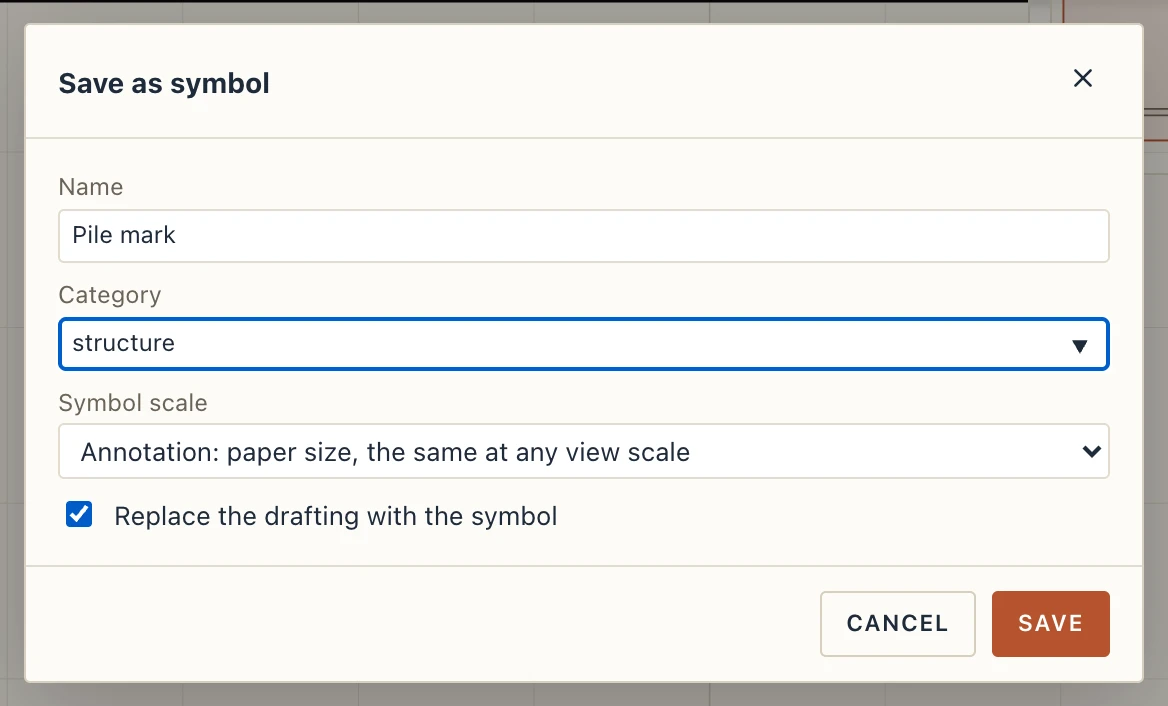
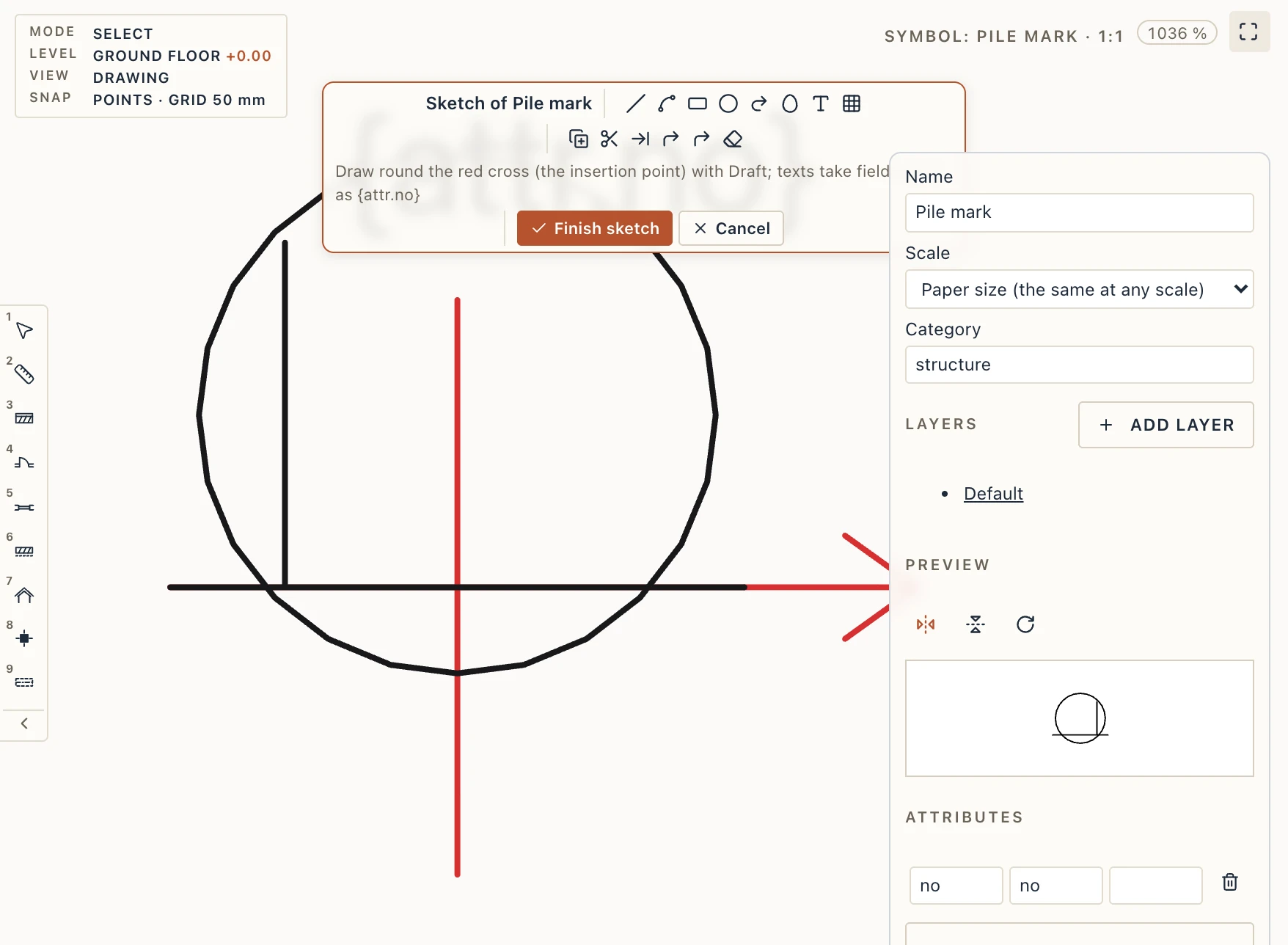
Draw the symbol in a plan, section or drafting view with the ordinary tools (lines, circles, texts). Where a text should change from copy to copy, write a live token in it, such as {attr.no}. Select the drawing, then choose Draft → Symbol → Save as symbol… (or type SAVESYMBOL, or right-click → Save as symbol…). Click the insertion point (the point that lands where you click when you place it), then click a point along the symbol's direction (its +x axis, which a section head follows when it turns), or press Enter for 0°. A small dialog asks for the Name, the Category and the Scale (annotation or model). With Replace the drafting with the symbol ticked, your drawing becomes one placed symbol where it was; one step of undo brings the lines back.

The symbol editor
Manage → Symbols… lists the symbols (below). New, Edit… and Duplicate of a built-in symbol open the symbol on a board: a drawing view of its own, in the symbol's millimetres at 1:1, with the insertion point as a red cross and an arrow along +x, the symbol's direction. The sketch bar at the top has the Draft tools (Line, Polyline, Rectangle, Circle, Arc, Ellipse, Text, Hatch; Offset, Trim, Extend, Fillet, Chamfer, Erase), Finish sketch and Cancel. Snaps and grips work as on any view, and so do the ribbon's Draft tab and the command line. A panel beside the board keeps the symbol's fields: Name, Scale (paper size / model size), Category, the layer new items go on (when the symbol has layers), a turned or flipped preview made by the engine, the attributes table and the fields. Finish sketch writes the symbol in one undo step: every placed copy follows, and what you did not touch stays exactly as it was. An ellipse becomes its points (symbols have no ellipses); construction lines are helpers only and are not kept; a dimension or other annotation on the board must be deleted before Finish sketch. Cancel drops the edit. Symbols of this computer's library are edited the same way.
Tables in a symbol. Annotate → Table on the board puts a table into the symbol (and Save as symbol takes tables among the drafting). Its cells read each placed copy's values, {attr.name}, {= attr.area | 0.00} m², and in a tag's symbol the element's fields, {number}, {= area | 0.00}: each copy lays its own columns and rows, so a room tag drawn as a table grows with its name. Explode turns it into lines and texts.
Attributes are the values asked for when a symbol is placed. Give each a key (no), a label and a default; a text that says {attr.no} then shows the value of each copy. They are filled in the command line's bar while placing and changed later in Properties.
Layers. The board's panel, under Layers, holds the symbol's own layers: Add layer and Remove layer; a click on a layer's name makes it the active one, and what you draw new goes on it (what was there keeps its layer). Each layer has a Visibility and an Opacity that take a number (0–100; a visibility above 0 shows), true or false, an attribute ({attr.show}) or a formula ({= attr.w * 10}). They are worked out for every placed copy from its own attribute values, so one symbol can show or hide its parts: a door symbol whose swing shows only when its swing attribute says yes, a note drawn at half strength. Plans, sections, sheets, the PDF and the SVG draw each copy as its values make it.
Live text. A text can show what the model knows, written in braces. The panel lists them (with a search box); a click copies one, to paste into a text written with Text, and texts show their fields as typed: for example {view.scale} (the view's scale), {level.name} and {level.elevation} (the level), {point.elevation} (the height of the point where the symbol stands: in a plan the level's, in a section or an elevation the height of that point), {mark.name} and {mark.number} (a view mark's). A formula starts with = and ends with an optional format after |: {= attr.w * 2 | 0.00} doubles the attribute w and writes two decimals. Formulas use numbers, the operators + - * / %, comparisons, the functions min, max, round, if, clamp, sin and the like, and names; they never run code.
Placing a symbol
Choose Annotate → Symbols → Symbol (or type SYMBOL, SYM) in a plan, a section, an elevation or a drafting view. A ghost of the symbol follows the cursor; click to place it, and keep clicking for more copies. Esc ends the tool. The command line's bar has the symbol to place, the turn button, the two flip buttons and one box per attribute. Space turns the symbol a quarter; type R and Enter to turn it, X or Y and Enter to flip it left to right or top to bottom. Whatever the turn or the flip, texts stay readable: left to right, or bottom to top when they have turned a quarter, never upside down or mirrored.

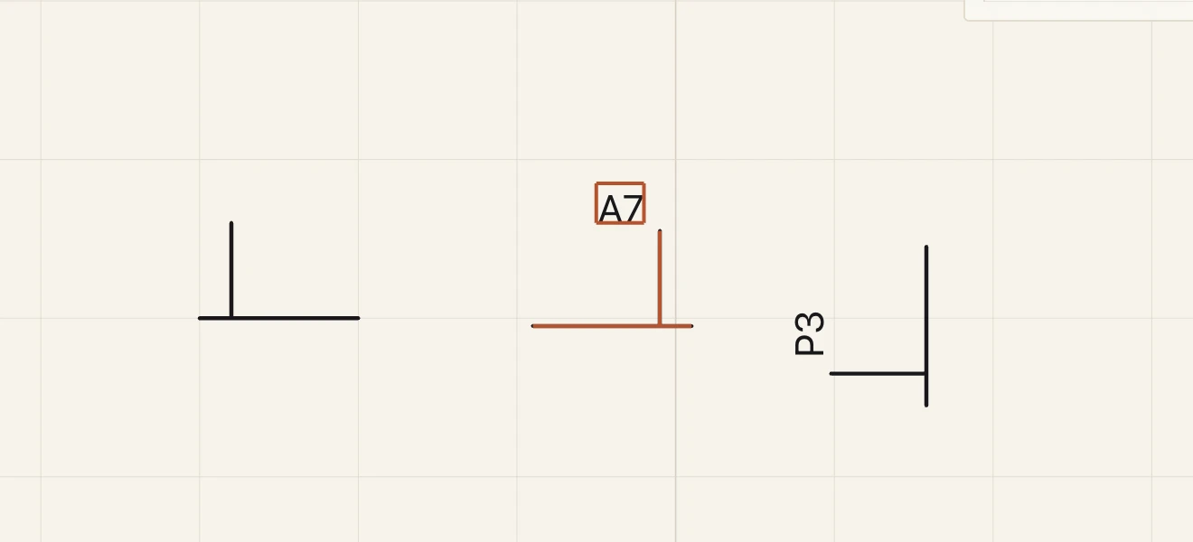
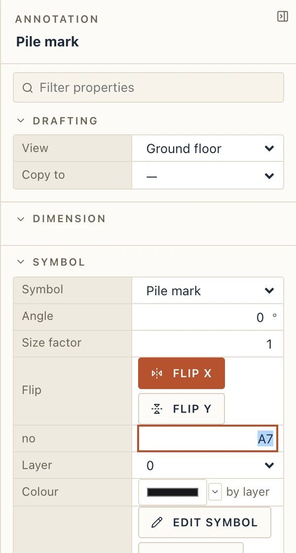
A placed symbol is selected like any element. In Properties → Symbol you can swap it for another symbol, set its Angle and Size factor, Flip X and Flip Y, change each attribute's value, choose its layer and colour, Edit symbol (the symbol itself: every copy follows) and Explode, which replaces the copy with plain lines, shapes and texts that you can edit one by one. Move, Rotate, Mirror, Copy and the other drafting tools work on a symbol like on any drafted element. A symbol belongs to its view, like a dimension, and sheets, the PDF and the DXF print it as you see it (in DXF it is a block).
Lapin's own symbols and yours
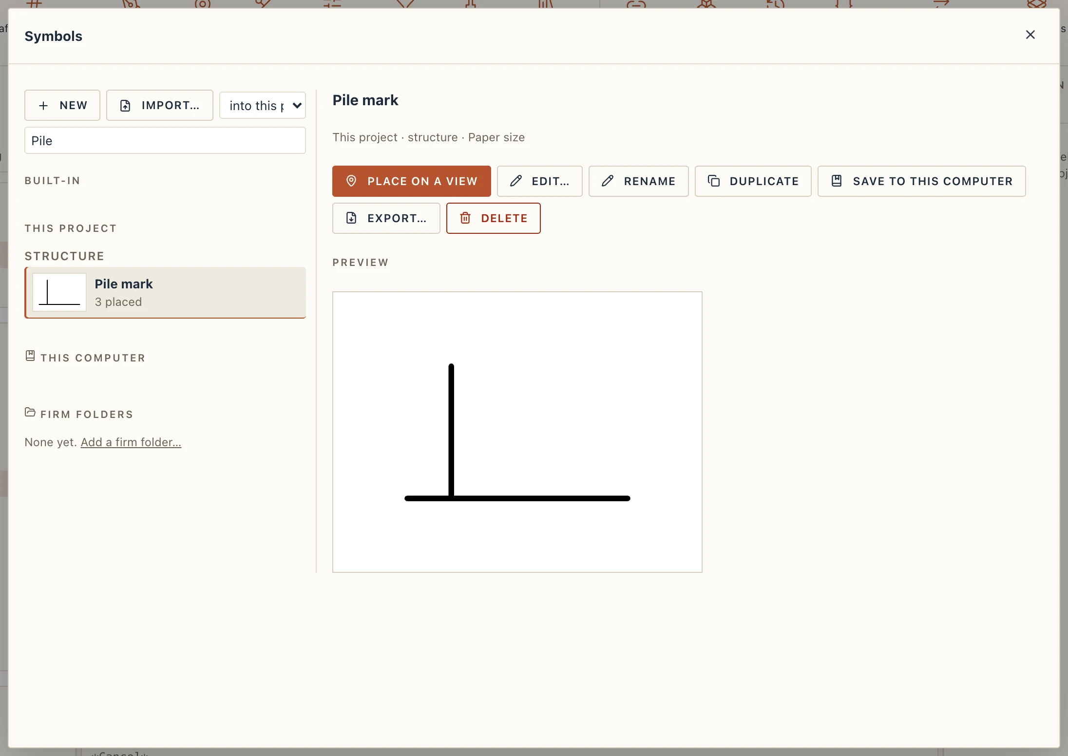
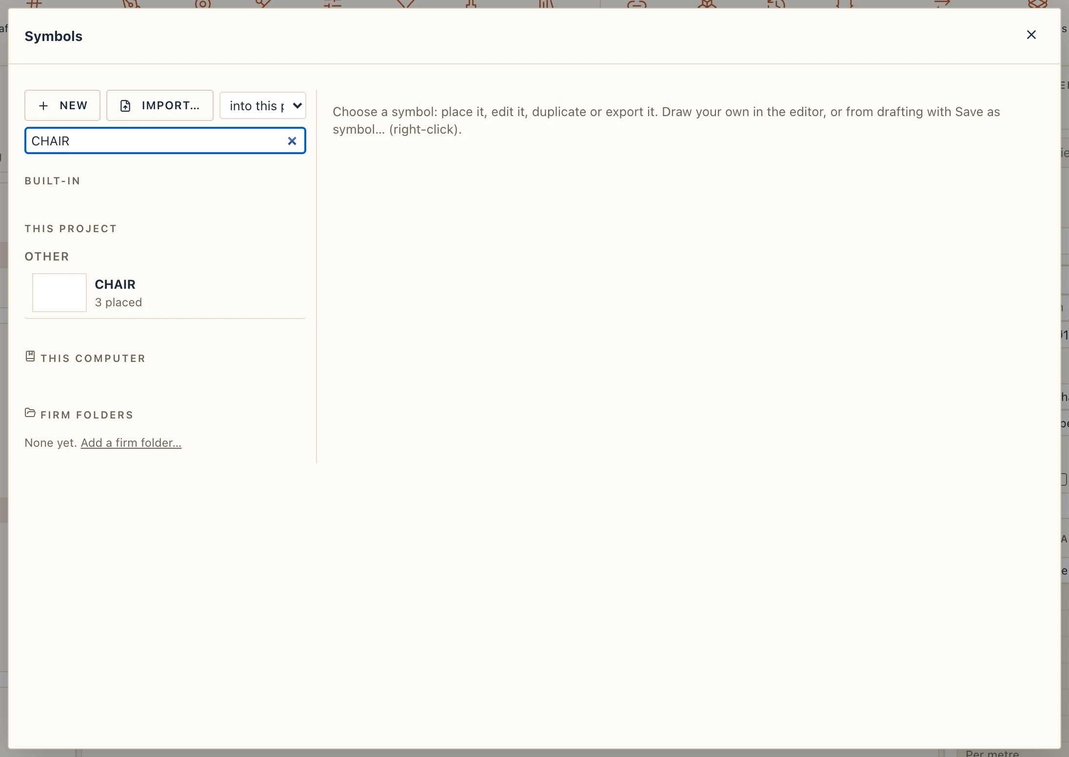
Manage → Symbols… opens the Place catalogue on the symbols, to place one; its Symbols… button opens the symbols' manager, which shows three places, by category. Built-in are Lapin's own: north arrows, the section head and the elevation mark with their numbers, the callout, the revision marker, the break line, the spot level, the level markers (half black and open) and grid bubbles. They cannot be changed, but Duplicate makes a copy of one in your project to change. This project holds what you made or imported; it travels in the project file. This computer is your library: Save to this computer puts a copy there, and every project you open on this computer can use it (Add to the project brings one in). Choose a symbol to see it large, and Place on a view, Edit…, Rename, Duplicate or Delete it (a symbol that is placed asks what to do with its copies).
Sharing symbols
Export… writes the symbol as a .lapinsymbols file; Import… reads one, into the project or into this computer's library (the box beside the button). Where the project already has a symbol of the same name drawn otherwise, the import preview lists it with a choice: Keep both (the default: the file's comes in as Name (2)), Replace (the copies placed follow) or Skip; see Importing a library file.
Marks of the views
Lapin draws the marks of the views itself: a section's head, an elevation's mark, a level's marker, a grid axis' bubble, a site plan's north arrow, a callout's head, a view's title on a sheet. You can have any of them drawn with a symbol of yours (or one of Lapin's own: a square grid bubble, a half-black level marker) and change them all at once.
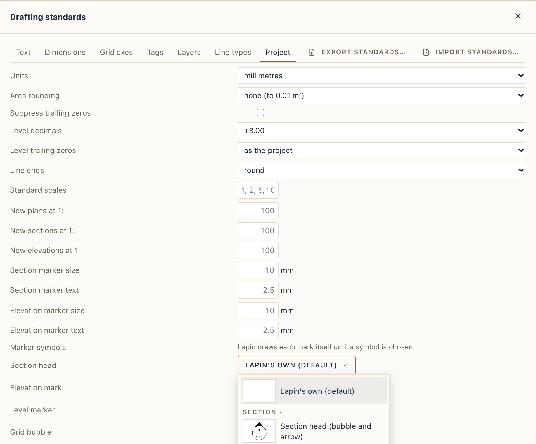
In Manage → Drafting standards → Project, the Marker symbols list has one picker for each: Section head, Elevation mark, Level marker, Grid bubble, North arrow (site plans), Callout head and View title (on sheets). Open a picker to see the symbols with their pictures, those of the mark's own kind first (the grid bubbles for the grid bubble), then the others. Lapin's own (default) keeps the drawing Lapin made until now; nothing changes until you choose.
A mark can have its own symbol. Select a section, an elevation, a level, a grid, a callout or a view and, in Properties, Marker symbol (a section also has View title) shows the project's choice; pick another symbol for this mark alone, or Project's choice to go back. Several marks of the same kind selected change together.
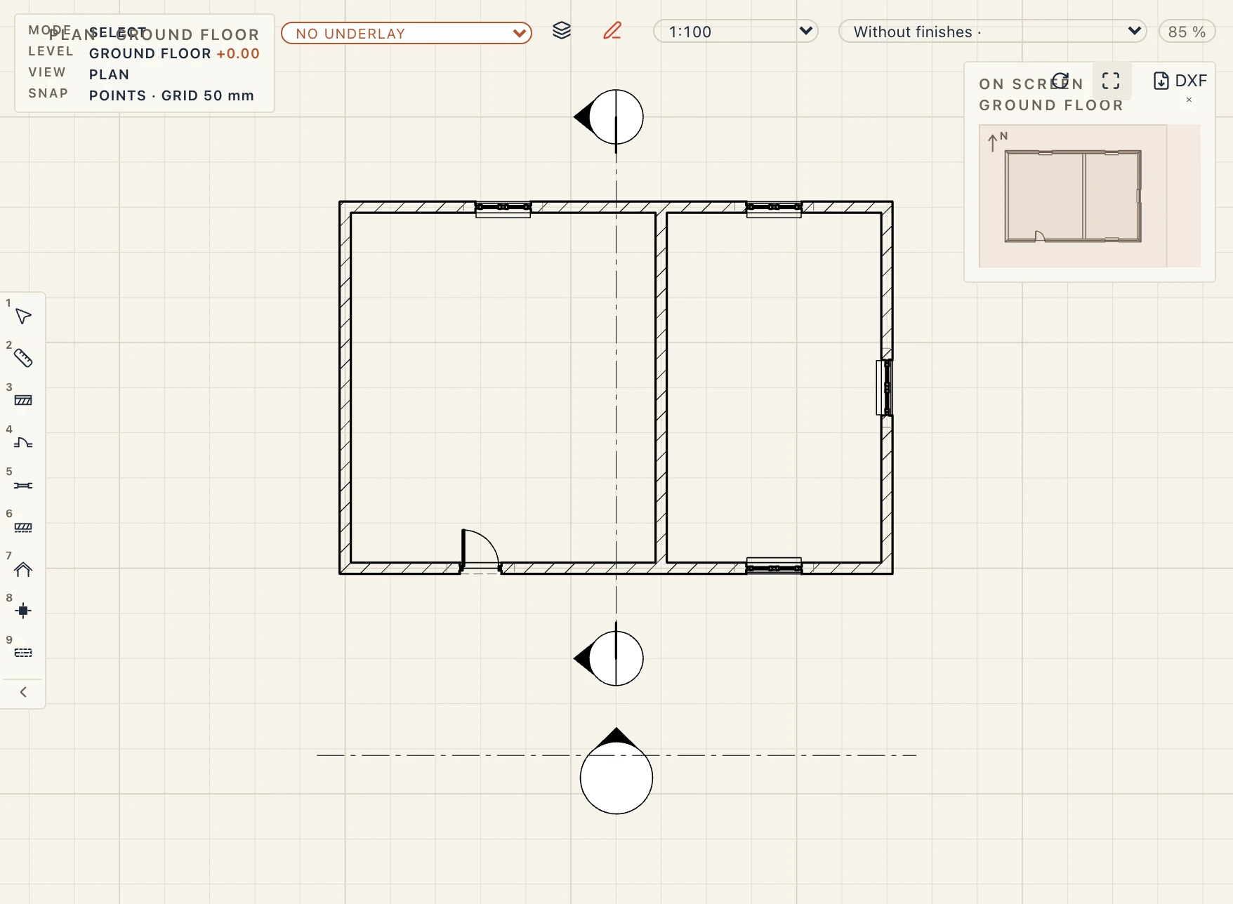
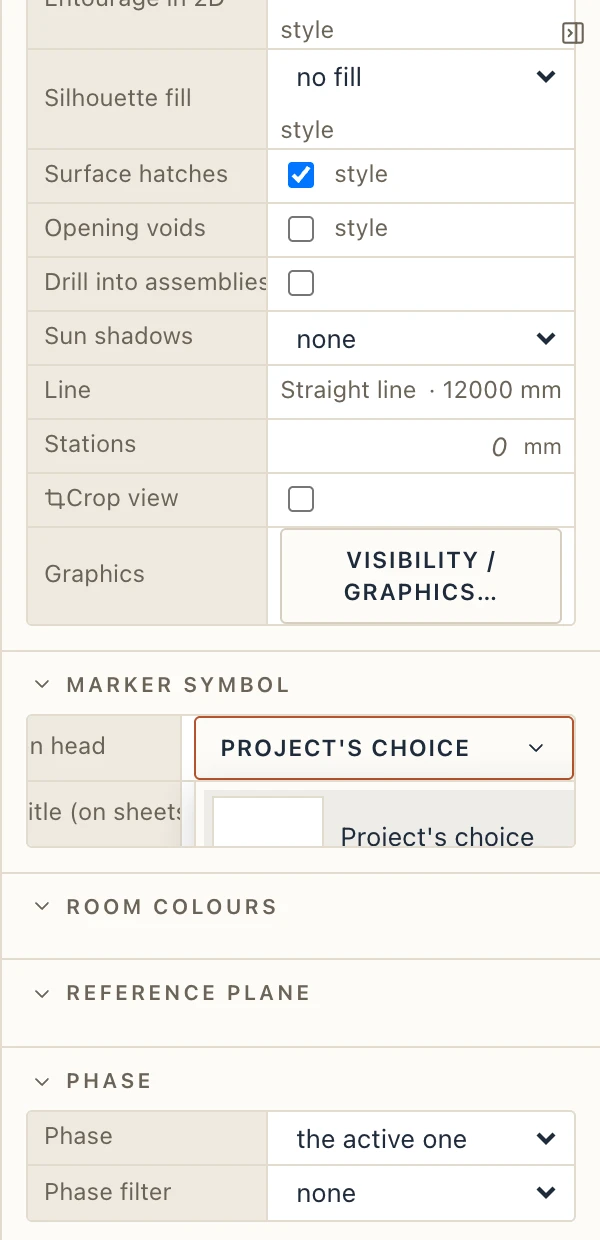
A symbol meant for a mark is made like any other (see above). Draw it with its +y pointing the way the mark points: a section head's arrow, an elevation's arrow, a level marker's triangle. It is laid along the section's or elevation's direction, on the grid's end, on the level line. The live texts of the mark fill it in: {mark.name} and {mark.number} (the view's number on its sheet), {mark.sheet} (that sheet's number), {mark.scale}, {level.name} and {level.elevation} for a level, {grid.label} for a grid axis; a symbol with the attributes number, sheet or name reads them from the mark. Lapin's built-in section head, elevation mark, callout, level markers and grid bubbles do.
Symbols on sheets
On a sheet, Place symbol… in the toolbar lists the symbols; choose one and click where it goes on the paper (Esc cancels). It is drawn at its paper size whatever the scale of the views on the sheet, and it prints as you see it.
Converting drafting to elements
Lines drawn in a plan, a drawing imported from DXF or traced from a PDF can become real elements. Lapin recognises what each shape is and makes it with the module that owns it.
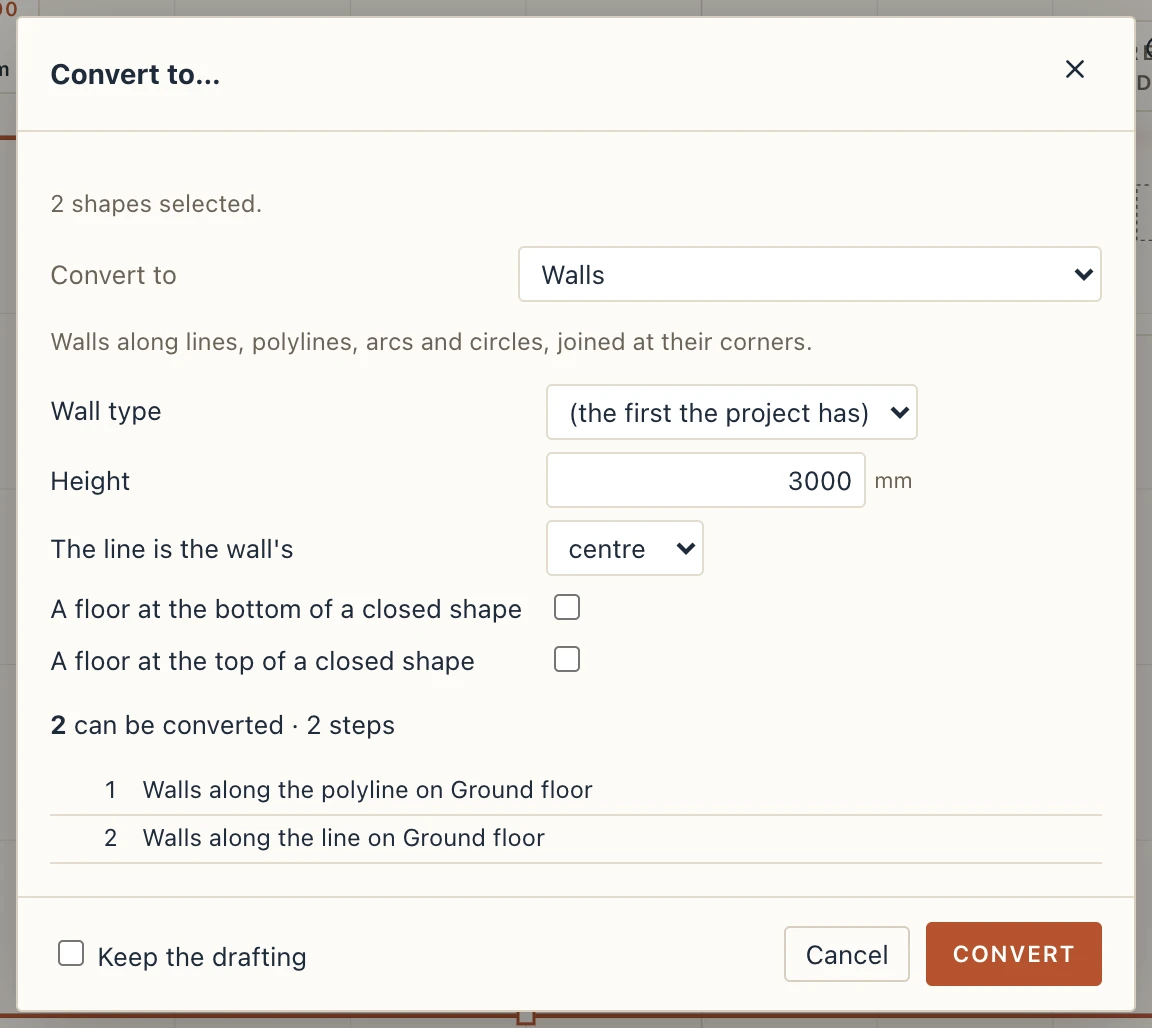
Draft → Convert → Convert to… works on the selection in the view in front: select drafted lines, polylines, arcs or circles first (right-click → Convert to… does the same). It is the one place where drawn shapes become something else; the dialog lists what they can become in your edition, grouped by module:
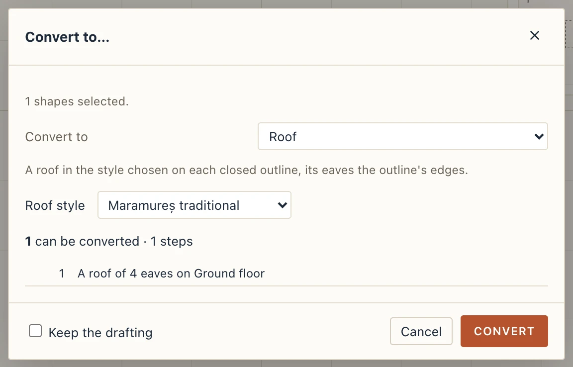
- Architecture: Walls (along lines and outlines, joined; a closed shape can have a floor at its bottom and its top), Floor and Ceiling (a closed outline; a circle makes a round one, by its arcs), Floor opening (a closed outline, cut in the floor under it; a circle makes a round one), Room (a closed outline), Roof (a closed outline, in the roof style you choose, its eaves along the outline's edges), Balcony (a closed outline), Stair (of the stair type you choose: a line or polyline is its path, the foot at its first point and climbing towards its second, turning the way the polyline turns; a closed outline's first edge is its foot and its width; the run and landings are the type's), Room separation lines (any line, polyline, arc or circle: see Room separation lines), Railing (an open line) and Skirting (a line or polyline, the board on the side away from the wall).
- Structure and Reinforcement: Beams, Strip foundations, Pad footings and Columns (a circle or an outline, turned along its longest side), and Reinforcement bars (a straight, L, U or stirrup shape recognised, else a polyline bar).
- Steel: Steel members (each straight piece, of the profile you choose, on the storey's top), Steel columns (where each circle or outline stands, of the profile you choose) and Steel members from outlines (a closed outline drawn as a band, as Convert to member reads it).
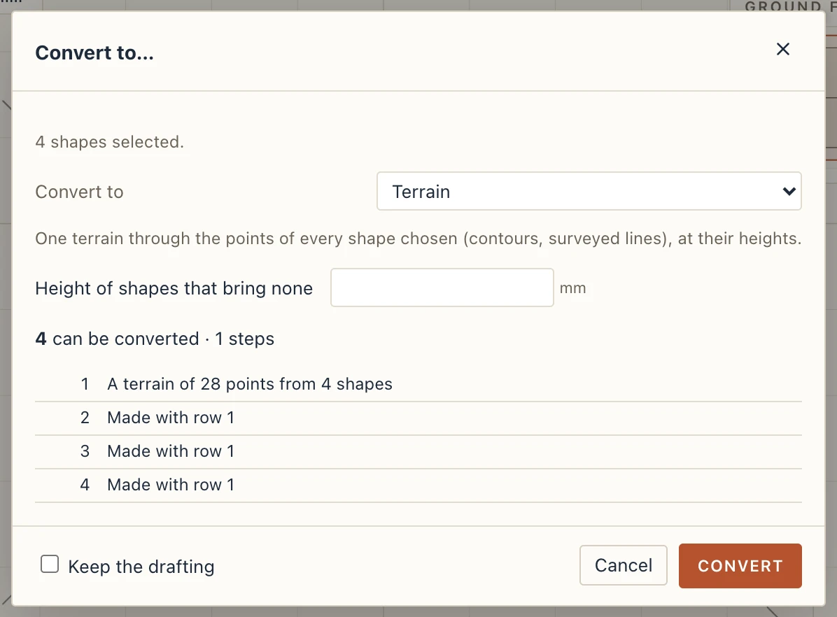
- Site: Terrain (one terrain through all the shapes chosen: a DXF's contours bring their heights, and you give one for shapes drawn without), Platform (a closed outline, levelled into the terrain), Parcel (a closed outline, the boundary of the terrain under it, in place of the parcel it had; its arcs kept, a circle round), and Road, Path and Breakline (along lines that meet end to end, as Road from linework follows them).
- A definition, in its own dialog: Symbol…, Part… and Profile… hand the selection to Save as symbol, Make part from sketch and the Profiles dialog.
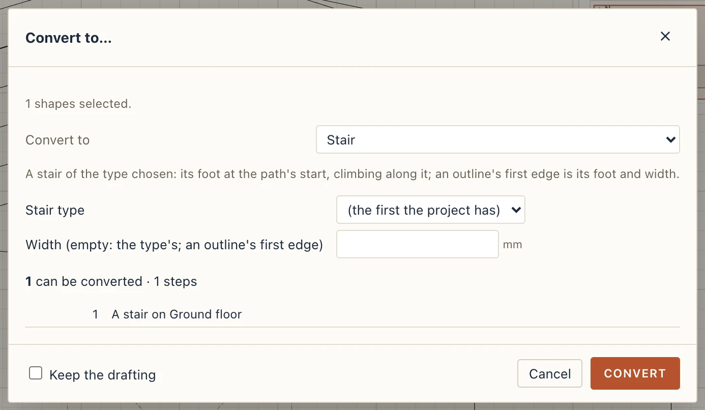
A roof, a balcony, a skirting and a steel member have straight edges only: an arc or a circle is refused for them, with the reason, and stays as drawn. The options of the chosen conversion (a wall's type and height, a roof's style, a profile) are below it, and the dialog says how many shapes can be converted and how many cannot, with the reason (a floor needs a closed outline), and lists what each would become; a shape that is part of another's element (a terrain's contours, a road's lines) says Made with row and that row's number. Plans take the plan's storey; sections and elevations take bars and steel outlines. Keep the drafting leaves the shapes under the new elements as an underlay; without it they are replaced. One step of undo brings the drafting back.
The tools that made elements from drafting elsewhere now open this dialog on their target: Steel → Convert to member on Steel members from outlines, Site → Road from linework and Breakline from linework on Road and Breakline. Studio's Ring, Box and Wall strip on a plan make their walls through the same conversion, keeping the drafting.

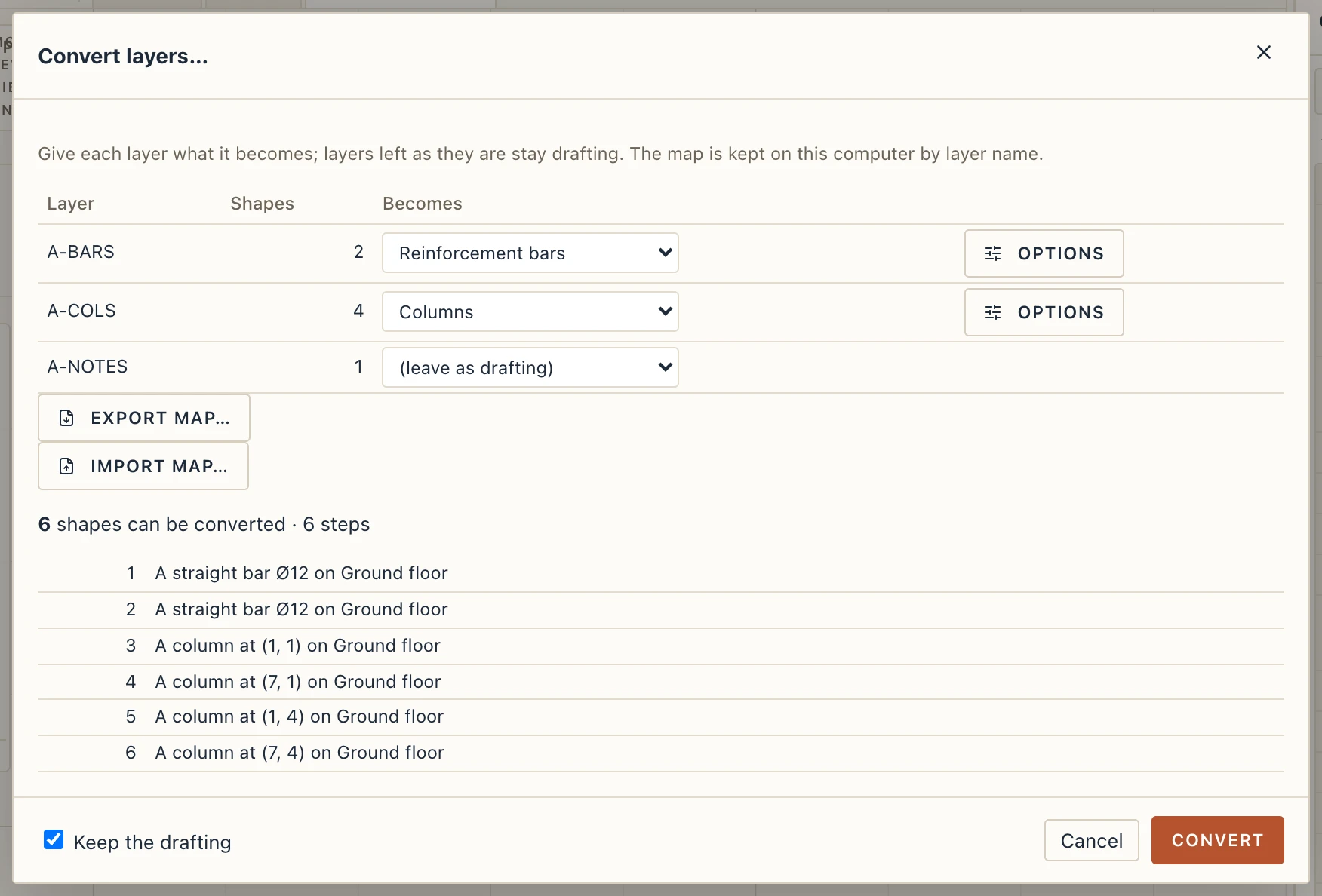
A drawing in layers is converted layer by layer: Draft → Convert → Convert layers… lists the layers of the view with their number of shapes and a Becomes choice for each: A-WALL to walls, A-COLS to columns, A-BARS to bars; (leave as drafting) keeps a layer as it is. The button beside a layer opens its conversion's options. The preview counts what will be made. Here the drafting is kept by default, as the underlay the elements were made from. The map is kept on this computer by layer name, so the next drawing from the same office is mapped already; Export map… and Import map… write it to a .lapinmapping file and read it back, to share with the office. After Import DXF… you can tick convert its layers to elements… to land in this dialog straight away.
DXF blocks as symbols
A DXF that has blocks (chairs, doors, a firm's symbols) can keep them: in the import dialog, Blocks → keep as symbols. Each block becomes a symbol of the project, at model scale, and each insert becomes one placed copy, turned and flipped as in the file; without it the blocks are exploded into lines. The blocks are then in Manage → Symbols… like any other symbol, where you can edit one and every copy follows, and a copy is selected, moved and counted as one element. The notice after the import counts the symbols and copies.
Line types
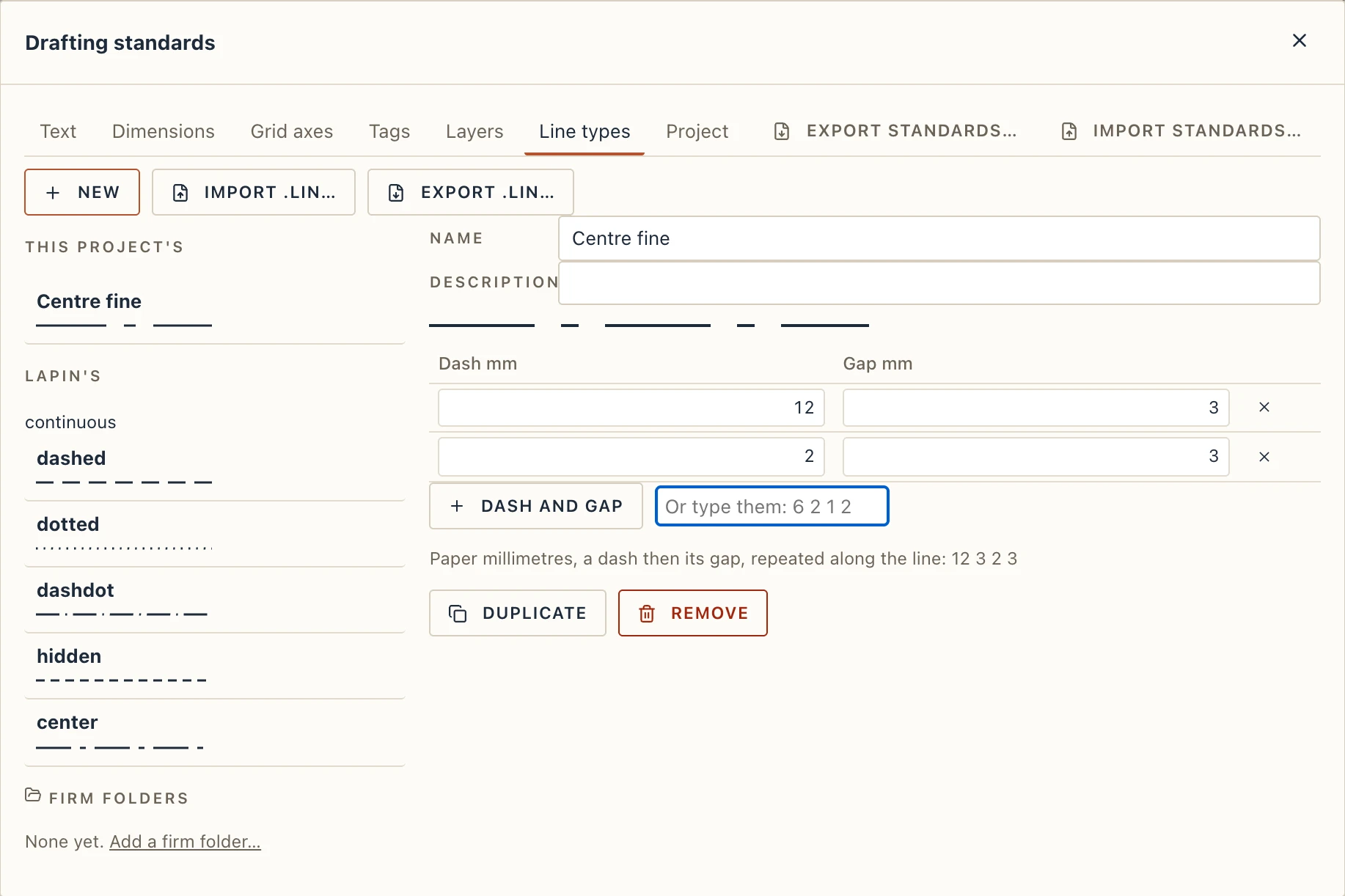
Dashed and dotted lines come from line types. Manage → Drafting standards → Line types lists Lapin's (continuous, dashed, centre, hidden…) and the project's own, each drawn as it prints. New makes one; choose it to change its Name and Description and its pattern, a Dash mm and a Gap mm repeated along the line, in paper millimetres, with a preview above. Dash and gap adds a pair, the cross beside a pair removes it, and you can also type them: 6 2 1 2 and Enter (a dash of 6, a gap of 2, a dot, a gap of 2). Duplicate copies a line type of Lapin's into the project to change. Renaming one renames it everywhere it is used: layers, grid axis styles, object styles, linework. Remove deletes it, and what used it draws continuous.
The project's line types are offered wherever a line type is chosen: drafting layers, the axes' and the object styles' line, linework.
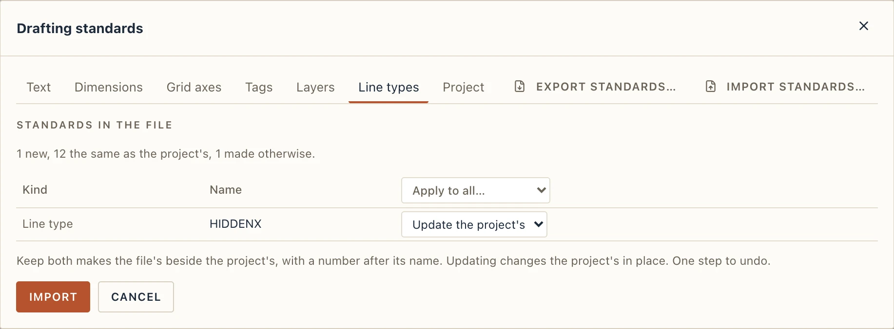
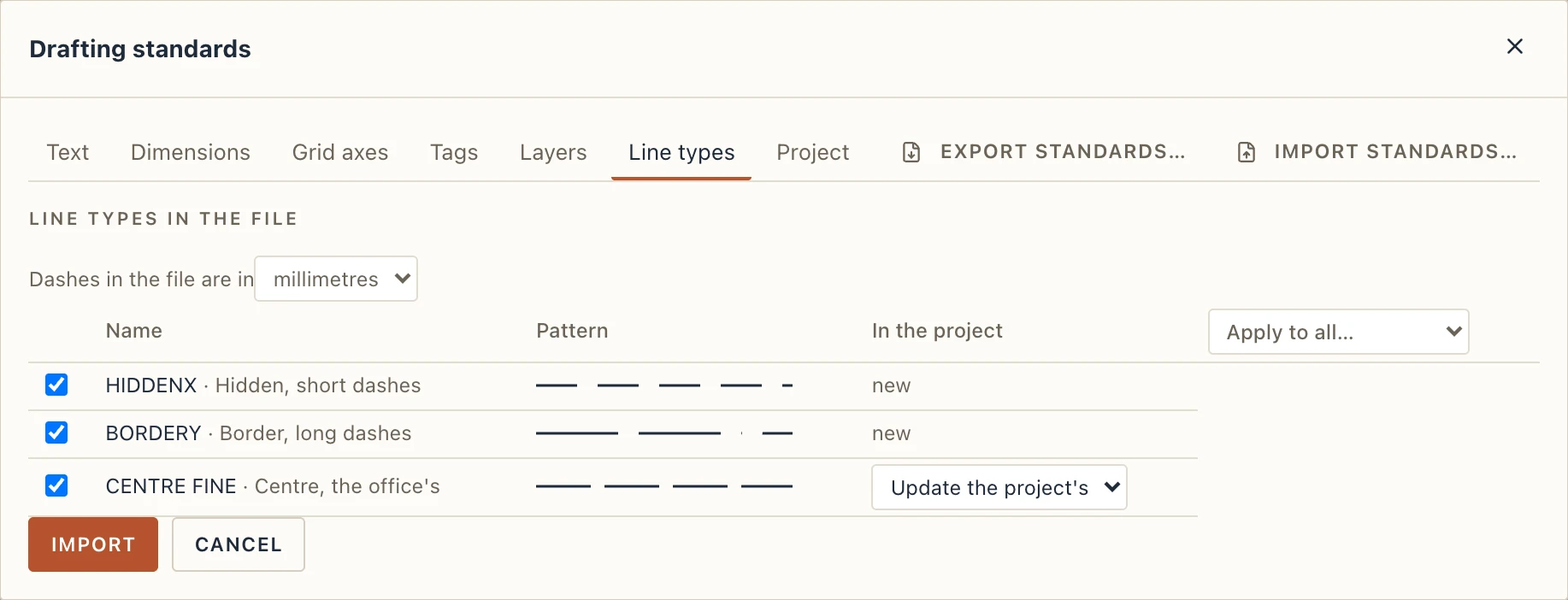
Import .lin… reads an AutoCAD line type file. The dialog lists its types with their patterns, Dashes in the file are in millimetres or inches, and a box for each to leave out. A type whose name the project already has with other dashes asks, as every library import: Replace (the default), Keep both (as Name (2)) or Skip, or Apply to all…. Text and shapes inside a complex line type are left out; its dashes are kept. Export .lin… writes the project's own types for AutoCAD.
The standards as a library
Export standards…, at the top right of Drafting standards, writes the project's styles, tag types, layers, line types, hatches and symbols as a .lapinstandards file: the office's standards, ready for another project or another computer. Import standards… reads one. What the project lacks is added; what it has but made otherwise is listed in the import preview, entry by entry, with the same choices as every library import (Replace, the default, Keep both, as Name (2), Skip, and Apply to all…). The file's options (units, scales, marker sizes, object styles, the pen table, marker symbols) come only if you tick Also the project's options…. A notice counts what was added, updated, the same and skipped, and one step of undo takes it all back.