User guide
Structure
Columns, beams and footings, their types, and how they meet.
The Structure tab holds the frame and the foundations.

Frame
- Column (CL): click where it stands. A column runs from its level to the level above.
- Beam (BM): click its two ends; with Arc in the command line's bar (Line / Arc), click its two ends, then a point the arc passes through. Curved beam (BC) starts the Beam tool already set to Arc.
- Columns at grid places a column at every crossing of the grid axes. To draw the axes, use Annotate → Grid axis (GR).
Foundations
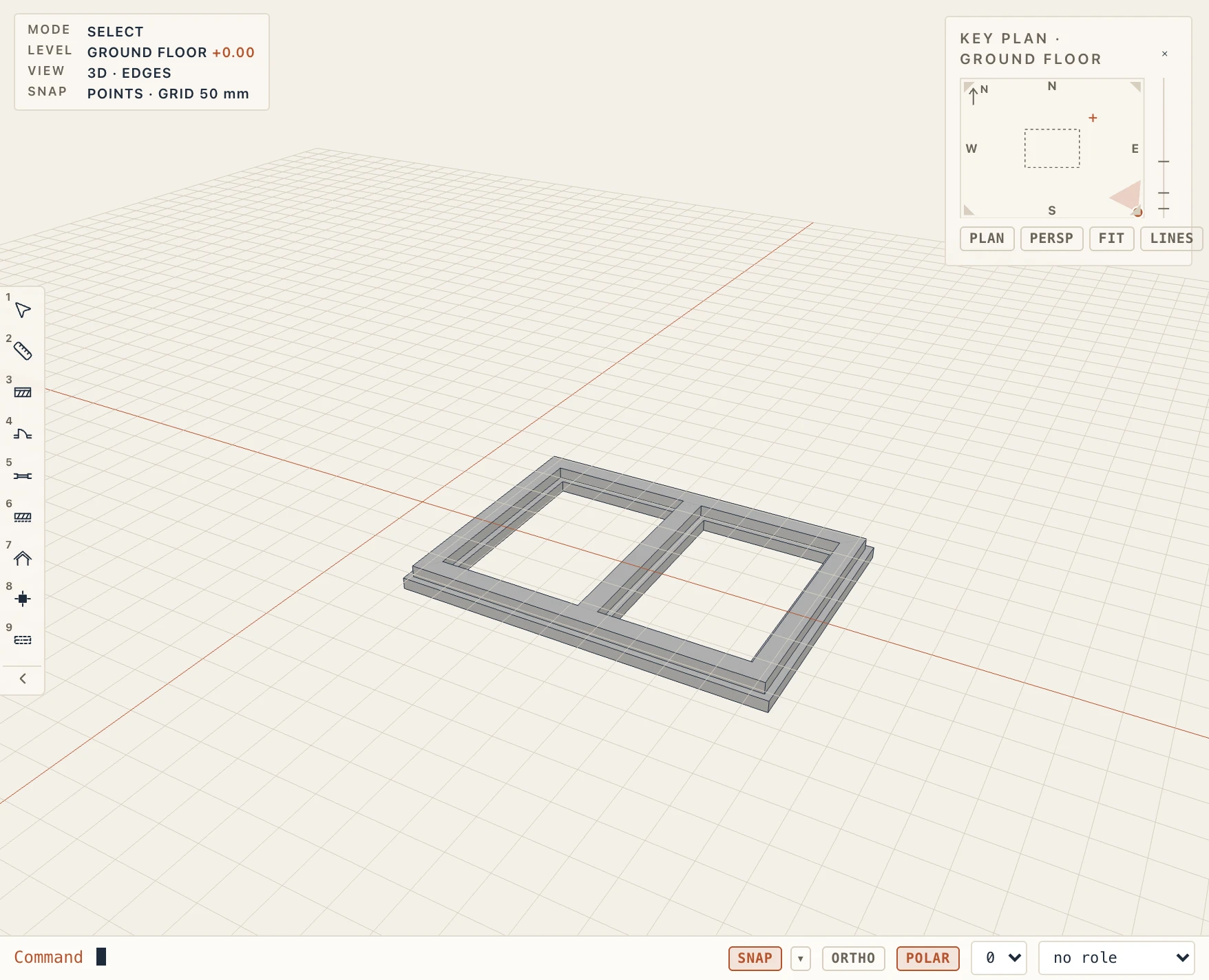
- Strip footing (SF) runs under walls. Its outer layers are mitred at the corners. Like the beam, it has Line / Arc in the bar; Curved strip footing (CF) starts it set to Arc.
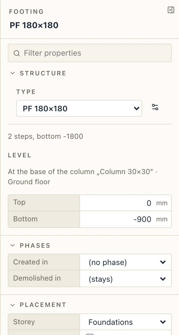
- Pad footing (PF): click under a column. While the tool is on, it snaps to the centres of the columns of the plan's level and of the level above.
- Pad footings under columns puts a pad footing under each selected column that has none, at its centre and turned with it. With no column selected, it takes the columns of the plan's level (in a foundation plan, those of the level above).
Draw foundations on the Foundations level, or give them a plan of their own.
A strip footing is the concrete alone unless you ask for the wall. While Strip footing is on, the command line's bar offers Footing alone (the default: a 600 × 400 mm concrete footing, a profile type made the first time) or With wall (the stem of a strip type on it, with its layers), and which strip type with a wall to use. The choice is kept. A footing already drawn changes with its type in Structure types.

In the plans. A footing lies under the floor, so a plan draws it dashed in the plan of the level it stands on, as a plan of a building shows what is under it. To see it cut and seen, use a foundation plan: in the project browser, the + beside Floor plans makes one for the active level (cut 0.50 m under it, seeing 2.50 m down).
Drawing in a foundation plan. It shows the level under it too, and what you draw there with a floor, wall, column or beam tool goes on that level (the Foundations of a new project, at −1.50); the footing tools keep the plan's own level. A pad footing drawn there under a column rises to the column's base; a strip footing's bottom is its type's under the level.
A pad footing rises to its column. A pad footing whose point lies within a column's section (to a millimetre) has its top on the column's base: the column's level plus its Base offset, the steps under it. Move the column, change its level or its base offset, and the pad follows. Under columns standing on one another it follows the lowest; of two as low, the one whose centre is nearest. A pad with no column over it stands on its own level, its type's Bottom under it. Pad footings under columns puts each pad in the highest level at or under its bottom (the Foundations of a new project), else in the lowest. A pad footing imported from an IFC file stays where the file puts it.
In Properties a pad footing shows its Top and Bottom as elevations and the column it follows. Type a Top to give it its own: it no longer follows the column. At the column's base links it back.
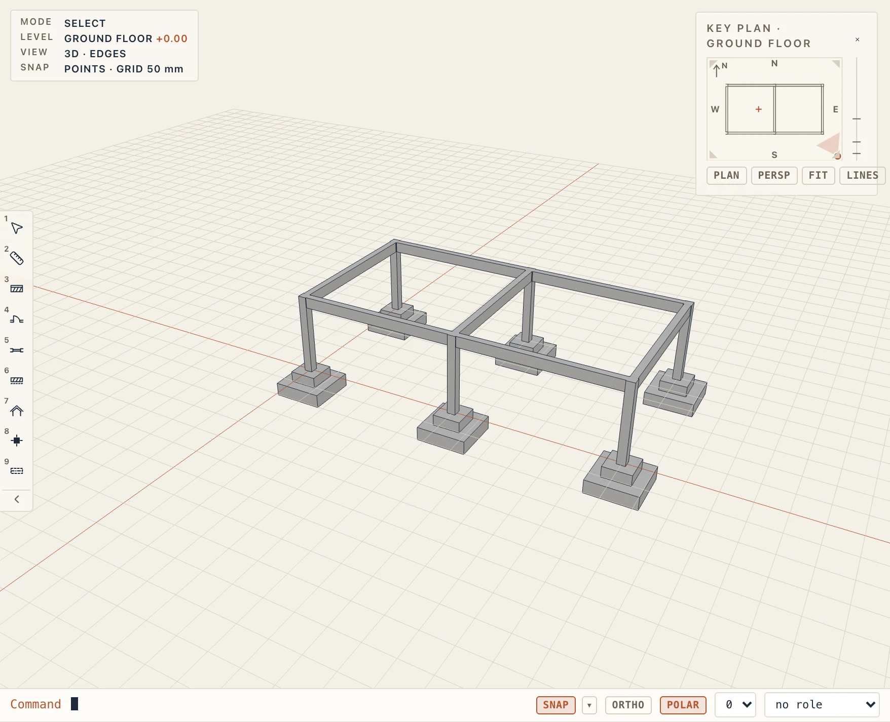
Beams and strip footings are cut and moved with the same tools as walls (see Trimming, extending, splitting and offsetting walls): Modify → Split element cuts one where you click it into two, Modify → Trim/Extend elements trims it back to a boundary or carries it on to one (a curved strip footing goes on round its circle; brought to another beam's axis, the two are joined), and Modify → Offset element copies it parallel, by its axis or between its faces.
Types and corners
Structure types sets the sections of columns, beams and footings: concrete sections and steel profiles. A column's Section is a Rectangle, a Circle or a Polygon, a regular one given by its Sides and its Diameter across the corners (an octagonal post, as an imported IFC may have it). Click a type in the list to change its size or its name, then Save type: every element of that type follows; New type goes back to making one.
Duplicate beside the name copies the type as „Name 2” („IPE 300 (2)” when the name ends in a number), and ↑ ↓ move it up and down the lists of its types, as in Wall types.
Beams and footings join by themselves where they meet, a corner as a mitre. A beam drawn from column axis to column axis stops at the columns' faces; its length, volume and stirrups count the clear span between them. Mitre, Butt and Swap (the Joins group, the same one that serves walls) change how two beams or two footings meet. Match properties (MA) copies one element's type and settings to others, and Create similar (CS) starts drawing another element of the same type.
Any other profile comes from the libraries: From a profile library… searches them all (see Profile libraries).
Types from a table
Import… under the list of column and beam types reads a CSV or an Excel workbook, one row a type: its name, its kind (beam, column or lintel), its profile, or its height h and width b for a rectangle, its material and mark, and for a lintel its bearing, manufacturer, code and the lengths it is made in. Lapin guesses each column from its heading, in English, Romanian, German, French or Czech (Název, Výška, Šířka, Uložení…), and reads a producer's export with columns such as height.value and height.unit; the dialog shows what it took, and you can give a field another column or another unit. A profile is looked for in the project, in your profile libraries and in Lapin's catalogue (IPE 300, HEA 240…); a row whose profile no library has is shown as not read. Rows that say no kind are what you choose (beams, columns or precast lintels). One type for the lengths of one section makes the rows of one section, material and maker whose names differ only by their length one type with all their stock lengths and the code of each (KP 7 - 100, KP 7 - 125… become KP 7 with 1000 and 1250); Lapin ticks it when the file has such rows.
The preview lists each type as New, Already in the project (left as it is) or Differs, with what differs (section, lengths, material…); for these you choose, as for the wall types, Update the project's (its elements and the lintels that use it follow), Keep both (Name (2)) or Skip. The import is one step to undo. Export CSV writes the types in the same columns, so a list can go to a spreadsheet and come back.
Beam types as lintels
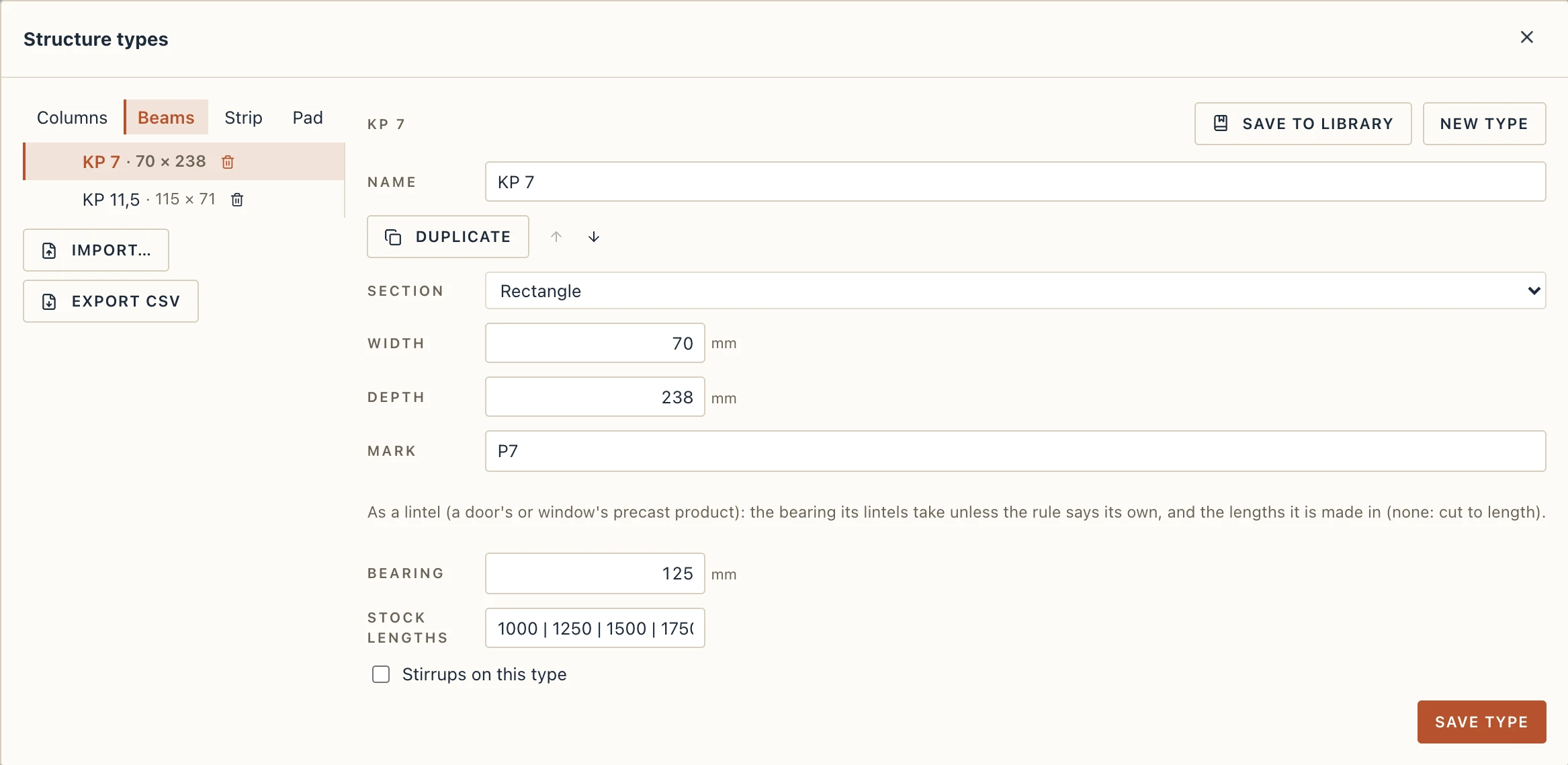
A beam type can be the product of a precast lintel. In Wall types or in a door's or window's configurator, Lintels → Precast, then the arrow, Product lists the Beam types first: the lintel takes the type's section (its width across the wall, its height), the shortest of its lengths that covers the opening and both bearings (a type with no lengths is cut to length), and its material unless the rule names one. Its bearing is the type's own: the bearing field shows it greyed, and a value typed there is the rule's own, until you clear it. Clicked in Structure types, a beam type shows its Mark, its Bearing and its Stock lengths (millimetres, separated by spaces or |) to change; the lintels follow the type. Importing a manufacturer's lintel catalogue (the button beside Product) makes each product a beam type too, so lintels and beam types are one list; products imported before still work.
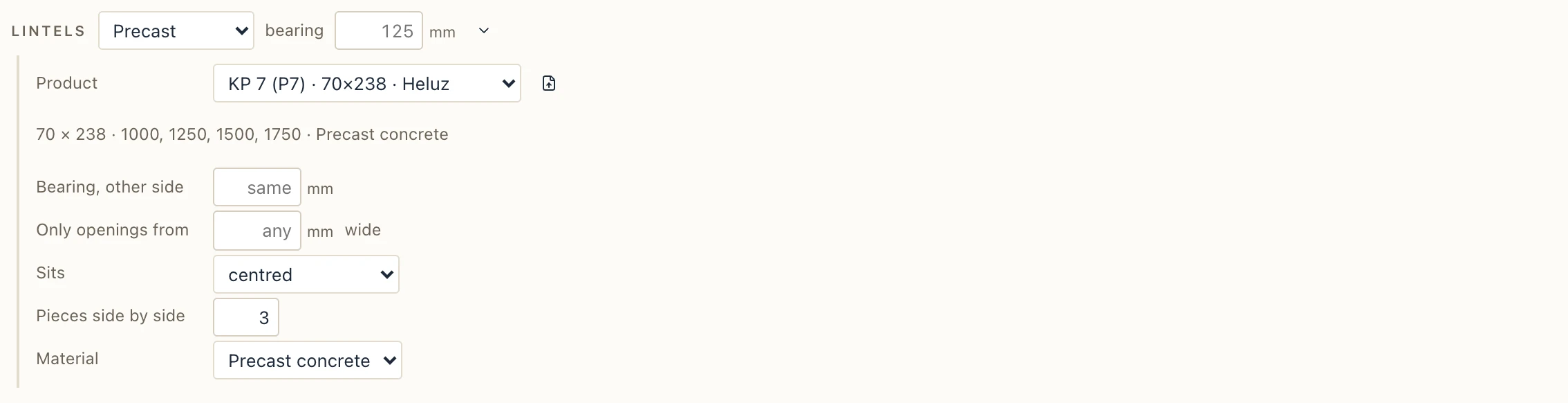
The lintels stay parts of their wall, as before; in IFC each is an IfcBeam LINTEL typed by its IfcBeamType, and the lintel schedule lists them by the type's mark and name, with the code of the length each takes.
Strip footing profile
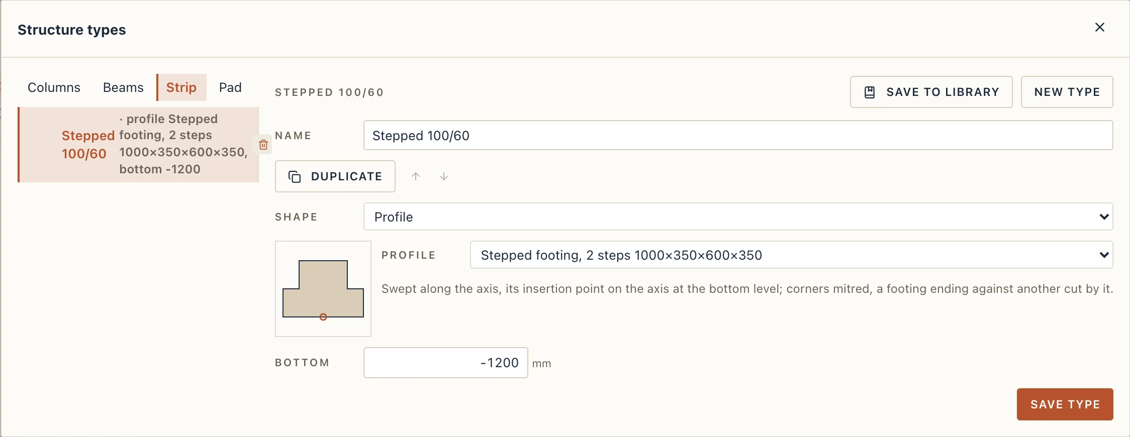
A strip footing type is either the standard one, a stem with its layers on a footing, or any profile swept along the footing's axis, as with Revit's footing profiles. In Structure types → Strip, choose Shape: Profile and pick a profile: one of the catalogue's (rectangular, stepped in 2 or 3 steps, with a sloped top, eccentric with its stem at one edge, with a stem), made with its sizes, or one of the project's (Manage → Profiles, where you can also type its corners or read a drafted outline). The profile's insertion point goes on the footing's axis at the type's Bottom level.
Profile footings run straight or curved. Two of them meeting in a corner are mitred, and one ending against another's run goes on into it and is cut by its body, so each step meets the other's step. Plans, sections and elevations cut the swept body. The quantities give its length, cross-section area and volume, and its upright sides are the faces Site works forms. In IFC a straight one is an IfcFooting STRIP_FOOTING whose body is its profile extruded (an IfcArbitraryClosedProfileDef), cut by the corners' planes; a curved one goes as its faces. Choose Standard to go back to the stem on a footing.
A structural view
A view's discipline decides what it shows. A Structure view shows the load-bearing cores only, without the finishes. You choose the discipline in the view's properties. See Views.
Loads
The Loads group holds what a structural analysis needs: load cases, area, line and point loads, and the combinations. See Loads.