User guide
Structural analysis
Run a linear static analysis of the frame under your loads, read the diagrams of forces, moments and deformation in 3D, and set the end releases of the bars.
Run analysis in the Loads group of the Structure tab (and in the Loads dialog) analyses the bars, slabs and walls of the model under the loads and combinations of Loads, and shows the forces in them.

What is analysed
- Bars (columns, beams, steel and timber members) are analysed with their own stiffness, from their material and section. A bar whose material has no modulus of elasticity is left out and listed.
- Concrete floors and slabs are analysed as shells: each is divided into small elements (a mesh, 0.5 m by default) that bend and stretch, sharing their nodes with the beams, columns and walls they meet. The slab carries its loads itself to what holds it, by its stiffness and theirs. A beam under a slab keeps its own axis below it and works with the slab as a T beam.
- Concrete load-bearing walls are shells too: they stand on their footings (a wall with nothing modelled under it is held along its foot) and carry the floors on them, and wind or other sideways loads in their plane.
- Masonry walls, and walls of other materials, are supports: they hold the slabs and bars on them, but are not analysed as walls.
- Floors of other materials (a timber floor) pass their loads to the bars and walls under them by the 45° rule: the corners' bisectors divide the slab into the areas each side carries, and each becomes a trapezoidal or triangular load on the bar below.
- Framed roofs pass the load to each rafter by its tributary width, half way to its neighbours; snow is taken per horizontal projection.
- Rods and ties (a solid round bar that braces, a tie or cable) work axially: they are pinned at their ends and their weight goes to their ends, so they do not sag as beams. A bar's Axial member in its Analysis properties changes it: By its section and use, Yes (a rod or tie) or No (a beam).
- Beams of different depths meeting a column each keep their own level; the column has one joint, and the beams are tied to it by a rigid arm.
- Wind on the façades goes to the beams, rails and floor edges along them; the strip at their foot goes straight to the ground and is listed apart from the bars' sums.
- The self weight of the bars is taken along them, and the loads you drew and the derived ones go where they find something under them. A load that finds nothing is left out and reported.
Running it
Choose Run analysis. The Analysis results dialog opens:
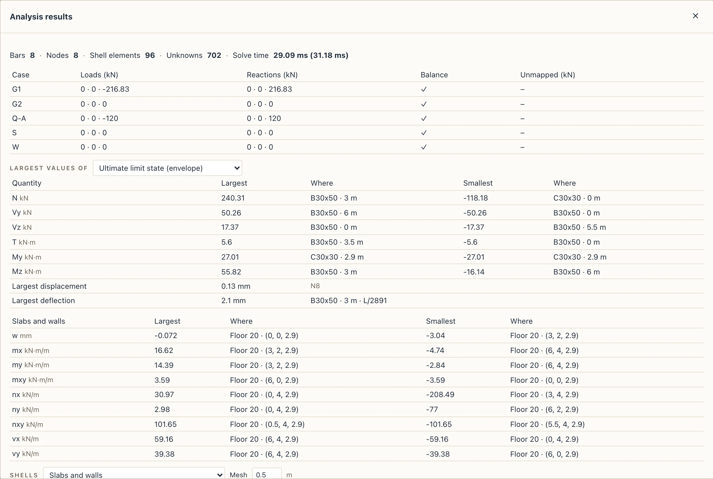
- The summary: the bars, shell elements, nodes and unknowns of the calculation and how long it took.
- For each case, the sum of its loads against the sum of the reactions, and whether they balance (a tick) or not (a cross: do not rely on those results). Unmapped loads are listed in kN.
- What was left out of the analysis, and why.
- The largest and smallest forces, moments, the largest displacement and deflection (with its ratio to the span, L/300) of the case, combination or envelope you pick; below them, the largest and smallest values on the slabs and walls, and where.
- Shells: which slabs and walls are analysed as shells (Slabs and walls, Slabs only, Walls only, or None: the slabs by the 45° rule and the walls as supports), and the Mesh size in metres. A smaller mesh is more exact and slower; a narrow piece always gets at least four elements across it. A change is one undo step; Run again takes it.
Show the diagrams closes the dialog and shows the results in the 3D view.
The diagrams in 3D
A card over the 3D view chooses what is drawn:
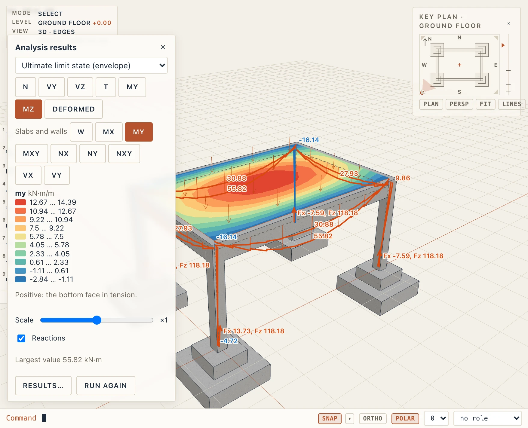
- What: a load case, a combination, or the envelope of the ultimate (ULS) or serviceability (SLS) combinations: the largest and smallest value at each point.
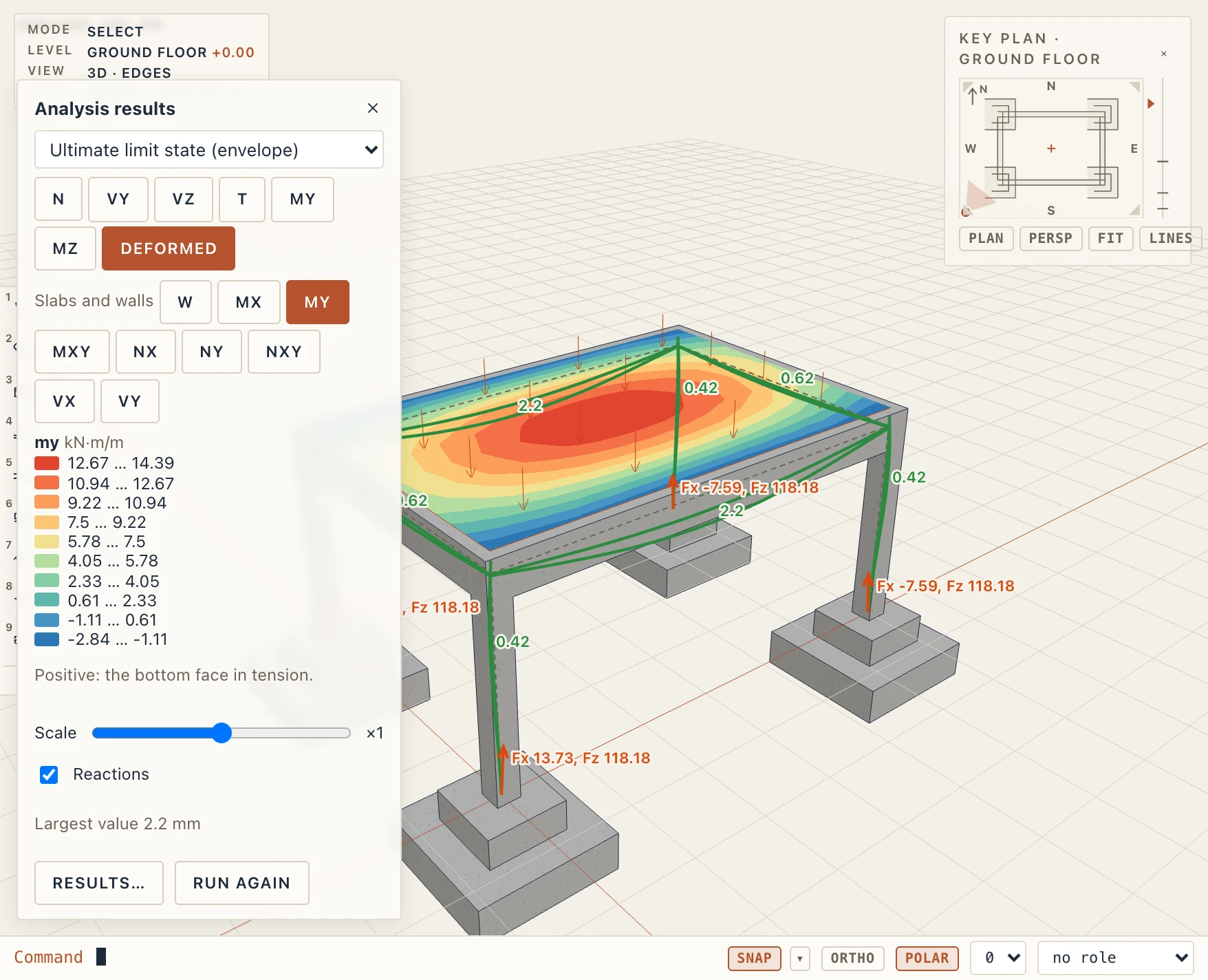
- Quantity: N axial force (tension positive), Vy and Vz shear forces, T torsion, My and Mz bending moments (Mz is the strong axis of a level beam, sagging positive), or the Deformed shape.
- Scale: the size of the diagram on screen; the model itself is not changed.
- Reactions: arrows at the supports with their values in kN.
Each bar shows its base line, the curve, hatch lines between them and the values at its extremes; red is positive, blue is negative. Moments are drawn on the side where the bar is in tension.
Slabs and walls
When slabs or walls are analysed as shells, the card has a second row of buttons, Slabs and walls, and the shells are coloured in bands by the quantity you choose (a second click on it takes the colours off):
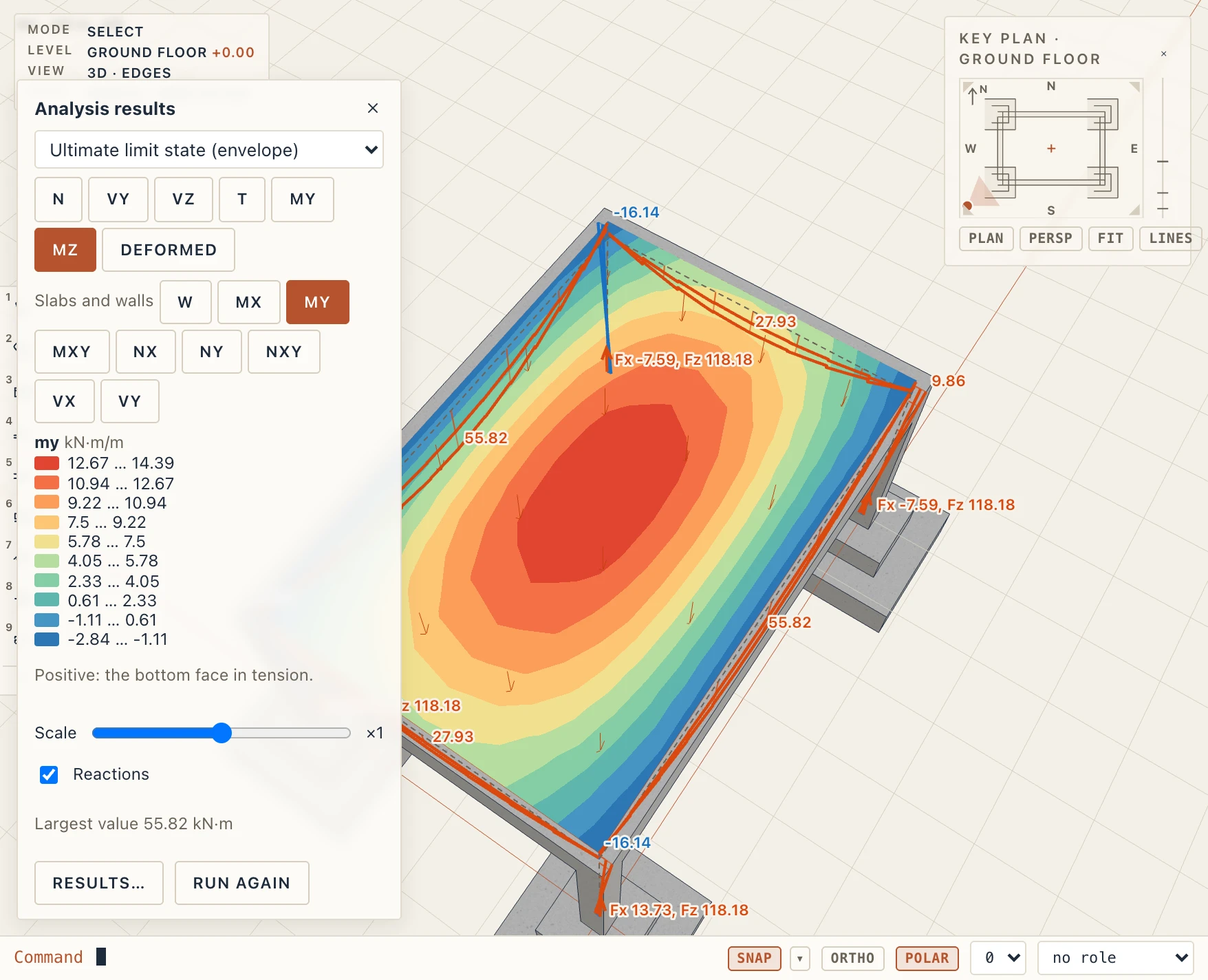
- w: the displacement across the slab or wall (up positive on a slab).
- mx, my: the bending moments in the slab's x and y directions (global X and Y on a slab; along and up a wall), in kN·m per metre. On a slab, positive means its bottom face is in tension (the span), negative its top face (over a support); on a wall, the face on the right of its direction.
- mxy: the twisting moment; nx, ny, nxy: the forces in the slab's plane (tension positive), in kN per metre; vx, vy: the shear forces across it.
The legend on the card gives each band's values and the unit:
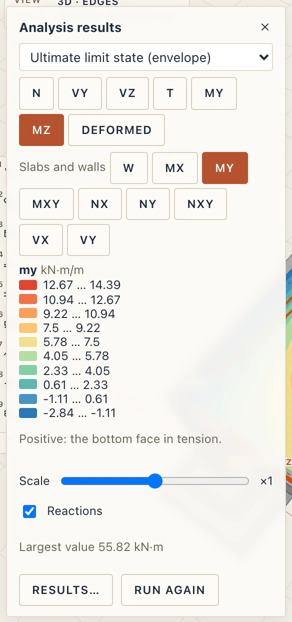
The same bands are drawn on the floor plan of the slab's storey, for the screen; sheets do not print them yet. For an envelope, each point shows the larger in size of its least and largest value.
End releases
Select a column, beam or member: its properties have an Analysis section with the Start (i) and End (j) releases.
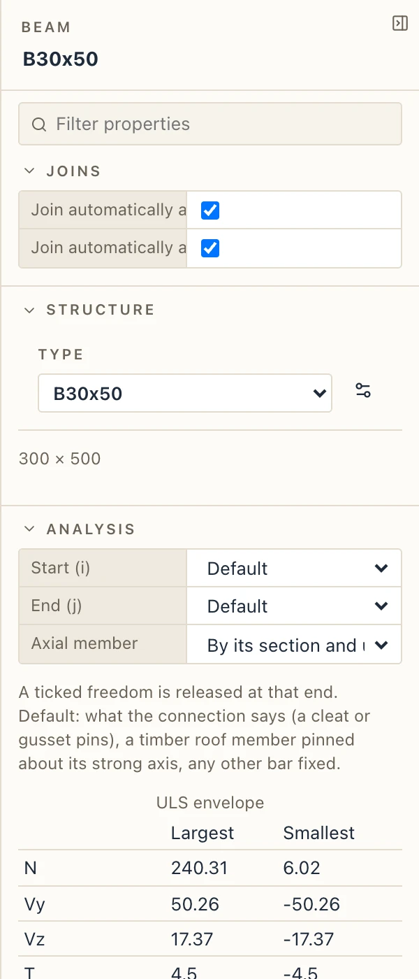
- Default: what the connection says (a cleat, a gusset or a fly brace pins the member), a timber roof member pinned about its strong axis, any other bar fixed.
- Fixed: the end carries moments. Pinned: it turns freely about both bending axes.
- Custom: six tick boxes, one for each freedom (displacement along the bar, along each shear axis, torsion, rotation about each bending axis); a ticked freedom is released.
A change is one undo step.
When the model changes
Results are worked out from the model as it is, never saved. When you change the model, the diagrams go off the view and the card says so:
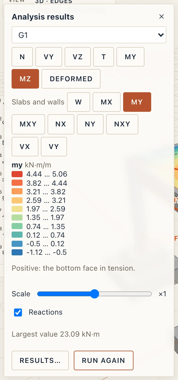
Run again analyses the new model.
A mechanism
If the structure can move without resistance (too many releases, or a part that nothing holds), the analysis stops and says where:
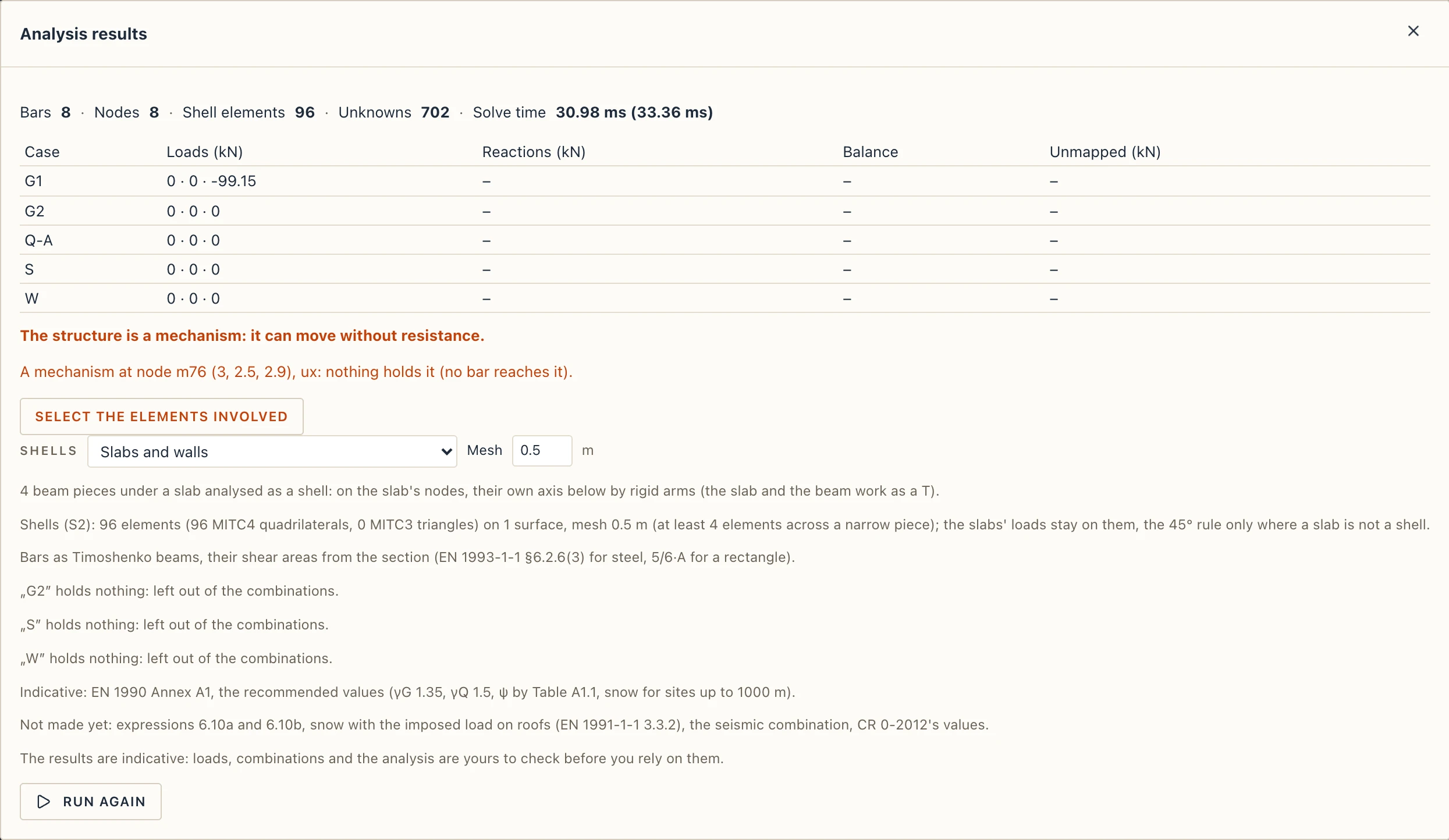
It names the node, the freedom and the bars concerned; Select the elements involved selects them so you can fix them, usually by fixing an end or adding a support.