User guide
MEP systems
Draw heating, water, drainage, electrical, ventilation, gas and fuel oil systems as schematics on the plan, with sources, endpoints and the runs between them, the gas supply in the street, and export them as an IFC network.
The MEP tab draws the building's services the way an engineer sketches them: a system per service, its source (a boiler, a water meter, a stack, a consumer unit, a fan), its endpoints (radiators, basins, WCs, outlets, lights, diffusers) and the runs between them. Every node is a real IFC element with its ports; every run is a pipe, duct or cable segment; the connections hold when you move things.

A system in one click
The MEP tab gathers its tools in three groups: System (New system ▾ with the services, Edit system, Systems…, MEP plan, Open ports and the Schedules ▾), Runs (Run, Place node, the run edits, Close the loop and the Street ▾) and Carriers and fans (Cable tray, the Fans ▾, Lay in carrier, Duct to outlet, Fan types). A button with ▾ opens its list; each tool keeps its letters, and Commands… and My tools find it as before.
Under New system, choose the service (Heating, Water, Hot water, Drainage, Electrical, Ventilation) and click in the plan. Lapin places the whole system: the source where you clicked, a first endpoint a few metres away, and the run between them. The system opens for editing.
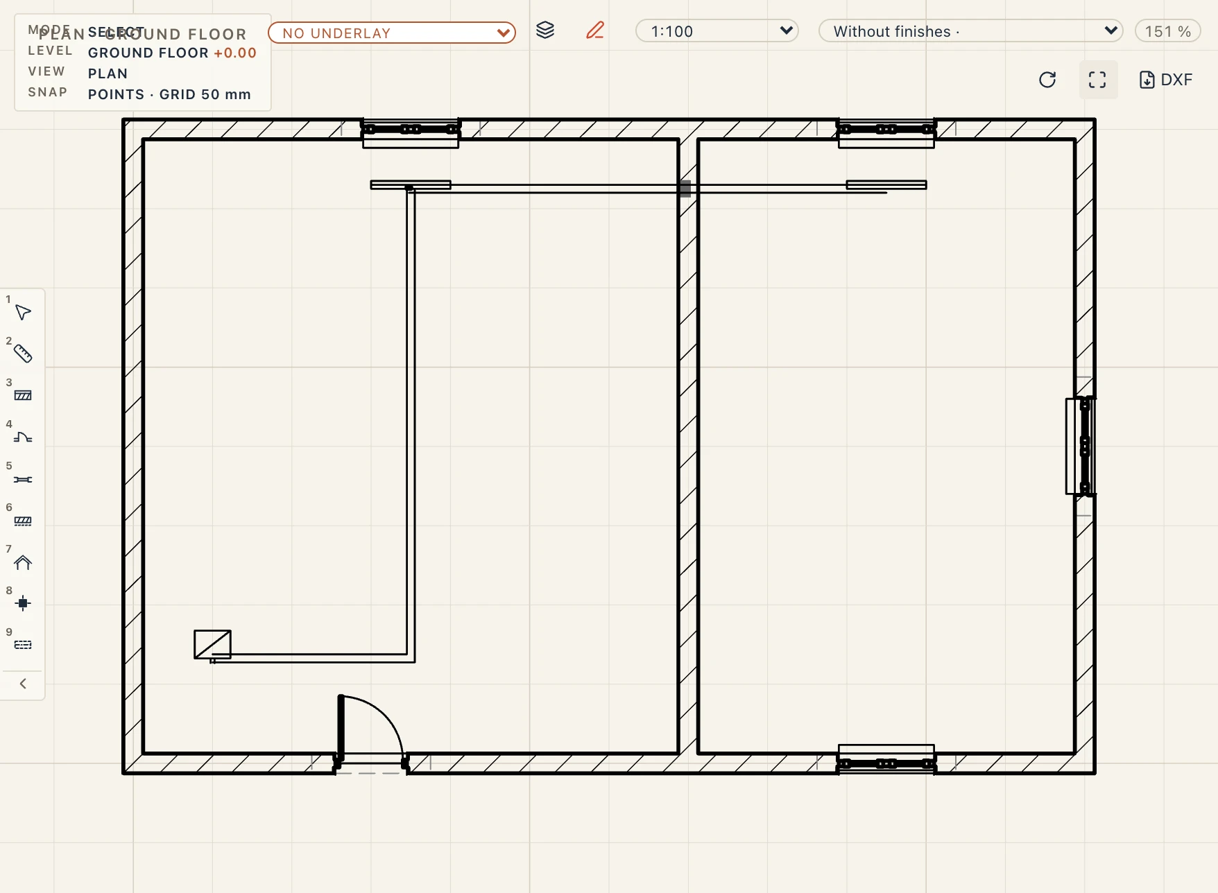
In the edit mode everything that is not the system is faded, and only the system's nodes and runs can be picked. Drag the source and the endpoint where they go: their run follows. Add endpoints with + Radiator, + Wash basin… in the properties panel, or with Nodes → Place node, which puts down any role you choose in the command line's bar (heating, plumbing, electrical, air, fittings, gas, fuel oil, fire alarm, fire hydrants; each role keeps its own letters, such as RA for a radiator): each new endpoint joins the system by a run of its own, from the nearest free port of the source, or from the nearest run (a tee). Done (or Esc) leaves the edit mode and tells you how many bends and tees the system makes and what is still open. Edit system (ES) opens it again.
Runs
Run (RN) draws a run point by point; press Enter to finish. An end that lands on an open port connects to it; an end that lands on a run of the same system branches off it.
Connect joins a run's end to a node or to another run; Disconnect frees it. Open ports selects everything still unconnected.
Reshaping a run
Select a run: its handles sit on the line as it is drawn, even after you move the nodes it connects.
- Drag a handle to move that corner freely.
- Drag the middle of a leg to slide the leg sideways; the legs next to it stretch, so a square route stays square. Slide the first or the last leg and Lapin adds a jog there, so the end stays on its port.
- Ctrl-click a handle to take it out, or the middle of a leg to add one; Add handle puts one where you click.
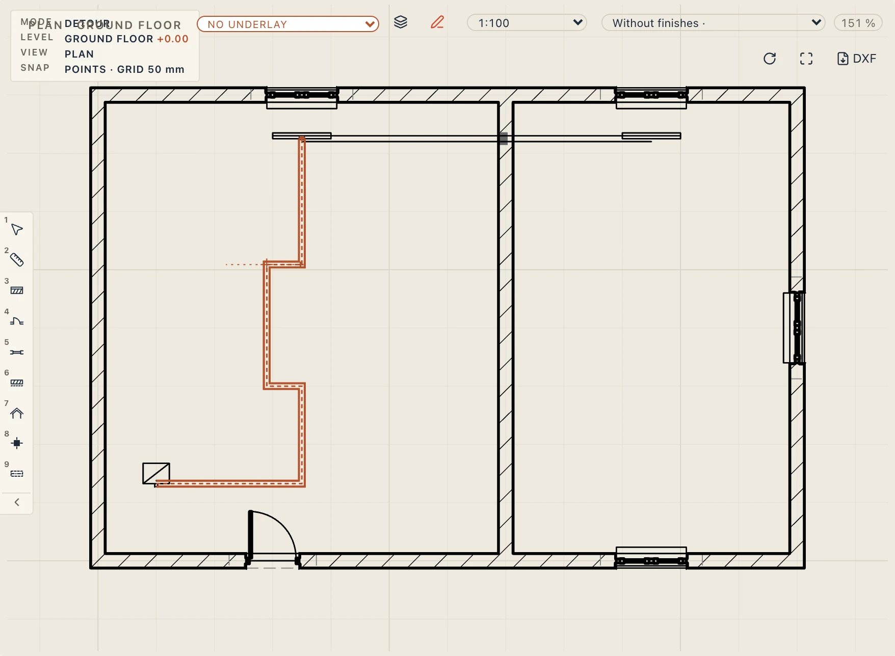
- Detour (DU) takes a run round something in the way: click the run where the detour starts, click where it ends on the same leg, then move to the side it goes and click (or type the distance). The run goes out, along and back, with four new corners; it keeps its connections.
- Redraw path (RP) gives a run a new route: select it (or start on it) and draw the path point by point, Enter to finish. The run keeps its system, its size and its connections, and its ends go back onto their ports.
- Modify → Split element cuts a run in two where you click: a coupling (an inline fitting, IfcPipeFitting CONNECTOR) joins the two parts at the cut, their ends at its middle, so their lengths add up to the run's. The second part takes what the run's end was on, and each branch stays on the part it joins. A paired run (supply and return) is left with two open ends there. Modify → Trim/Extend elements brings a run's end to a boundary (the end lets go of the port it was on), and Offset copies a run parallel. A branch on the part a trim cuts away refuses.
Nodes
Each node has a role: a boiler, a radiator, a manifold, a water meter, a basin, a sink, a WC, a shower, a bath, a stack, a cleanout, a consumer unit, an outlet, a light, a switch, a fan, a diffuser, an extract grille, a valve, a rise/drop, a cap. The role gives it its IFC class, its ports, its size and its symbol on the plan. A valve, a meter or a switch dropped on a run splits it and sits in the middle. A rise/drop takes a run to another elevation or to the storey above.
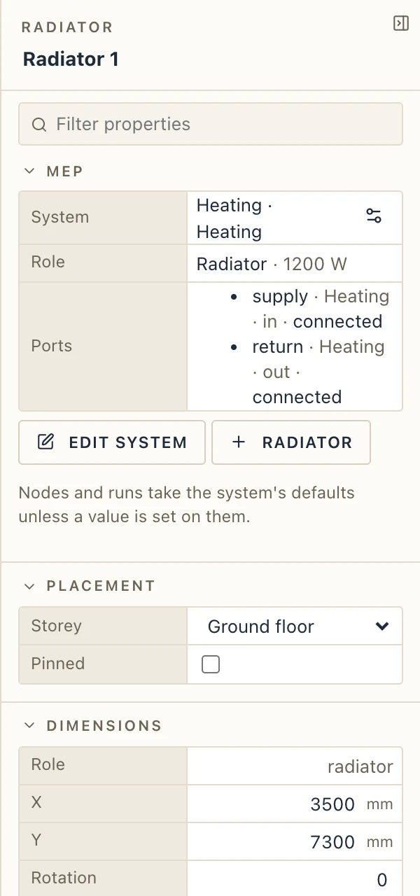
In the properties panel a node shows its system, its role and its ports (open or connected); a run shows its two ends. Both take the system's defaults unless you set a value on them: size, elevation, the plane they run in (floor, ceiling, wall), paired or single, material, slope.
Systems
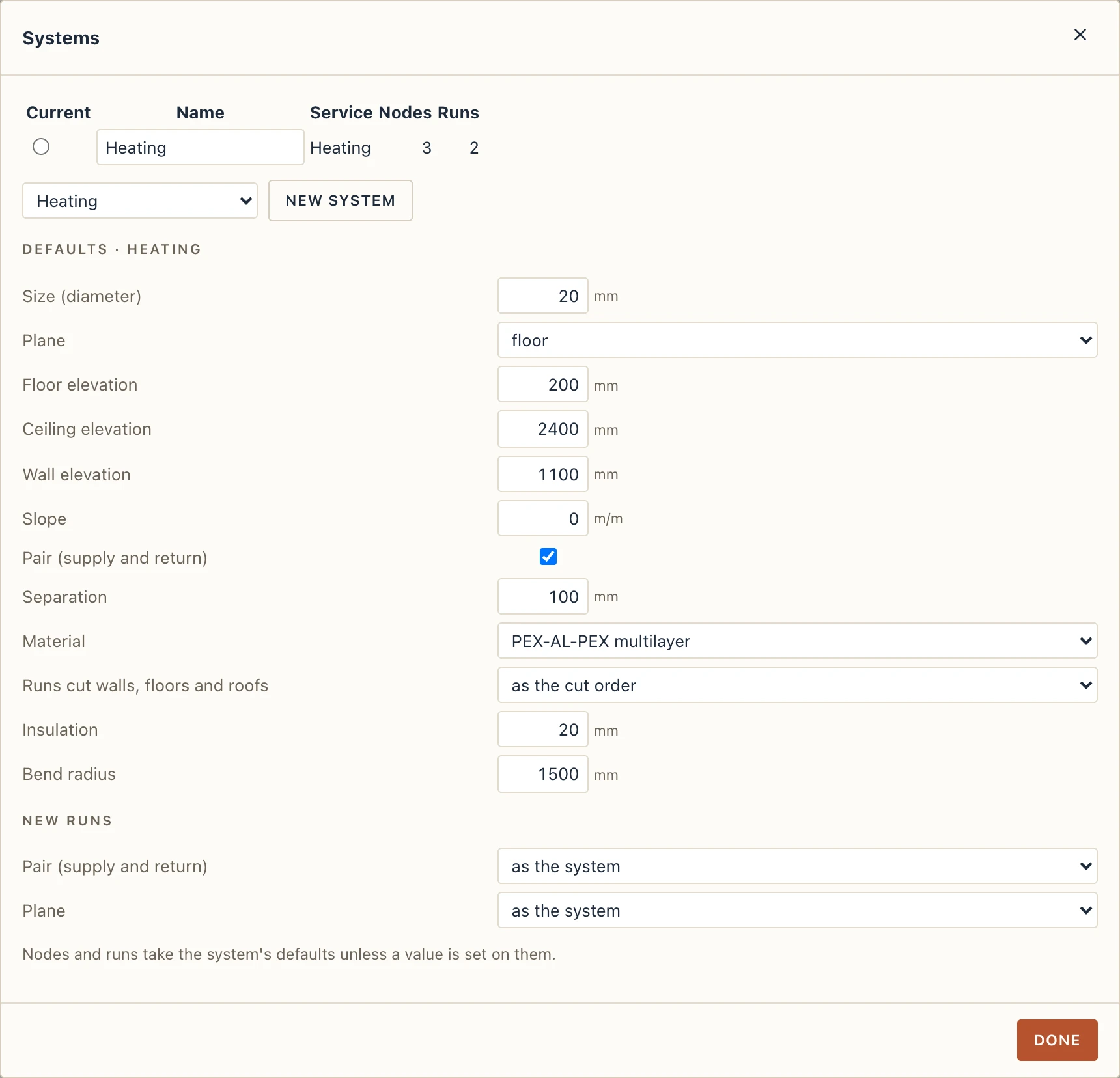
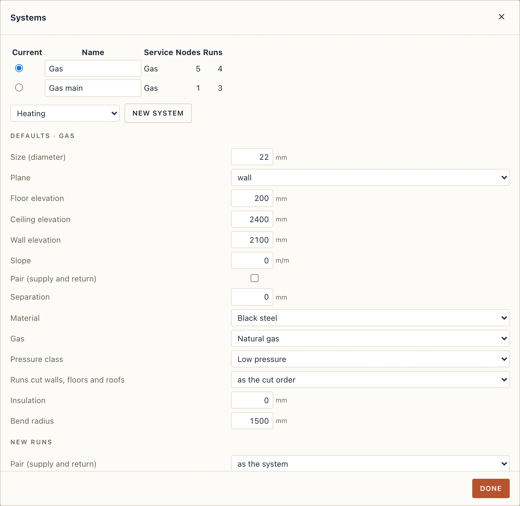
Systems… lists the systems of the project and the defaults of the current one: the size, the plane and the elevations of each plane, the slope (drainage), whether runs are drawn as a pair (heating: supply and return) and how far apart, the material and the insulation. Change a default and every node and run without a value of its own follows.
Plans, lists and IFC
MEP plan makes a plan of the MEP discipline for the level, filed under the MEP set in the browser. The Equipment list and the Run list under System → Schedules are schedules like any other: they go on sheets and export with them.
In an IFC export each system is an IfcDistributionSystem, every node and run has its IfcDistributionPorts, and the connections are written between the ports, so the network arrives in another program connected from the source to the last endpoint.
Gas and fuel oil
Gas and Fuel oil are services of their own under New system. A gas system says its gas (Natural gas or LPG) and its Pressure class (low inside the house, medium in the street) in Systems…; its pipes default to black steel on the walls at 2.1 m, and may be copper, multilayer or PE 100 for what is buried. Fuel oil runs in copper.
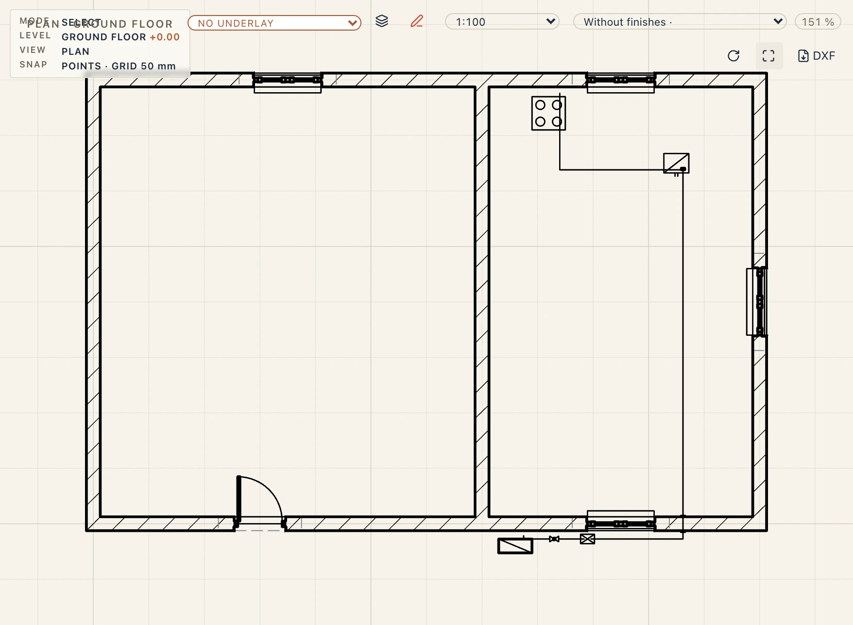
A house's gas installation starts at the meter box on the facade. Click New system → Gas: the meter box goes where you click and a gas boiler inside, joined by a run. On the way, the tools under Gas drop the gas regulator, the gas meter, the main gas shut-off valve, the appliance gas valves and flexible connectors on the run, which they split as any fitting does; the gas cooker and the gas water heater join the installation by a run of their own. Where a gas or fuel oil pipe crosses a wall it goes through a sleeve, drawn and counted with the run. A gas boiler drawn in the heating system as its source joins the gas installation from its properties (the + button with the gas system's name).
Each appliance keeps its consumption (m³/h) and its appliance type by its flue (A without a flue, B open flue, C room-sealed), for the lists and the sizing.
Fuel oil places a fuel oil tank (indoor, outdoor or buried) and an oil boiler; the fill point and the vent cap join the tank's own fill and vent, and the oil filter sits on the supply.
The supply in the street
Under Runs → Street, Gas main along… (GM) lays a gas main along what you click — a road, an alignment, a drafted line, a wall — at the offset from it and the depth (cover) set in the command line's bar; under a terrain the depth is taken from the ground, else from the level. Gas main draws one point by point. The main goes in a medium-pressure gas system of PE pipe, with its warning tape.
Service connection (GS): click the main, then the meter box. Lapin puts a tapping tee on the main, lays the service pipe square off it at its cover and on to the box, and rises into the box there.
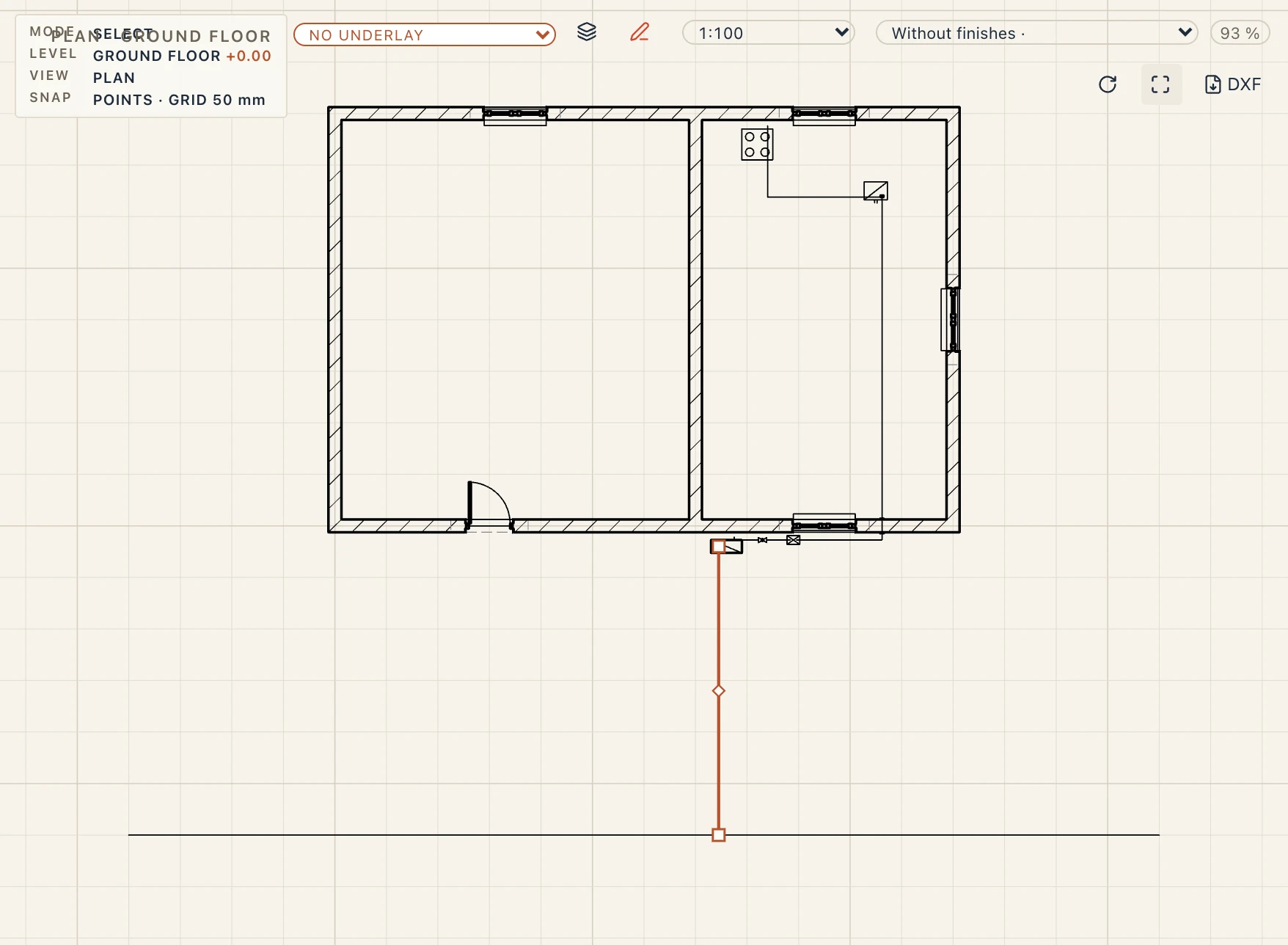
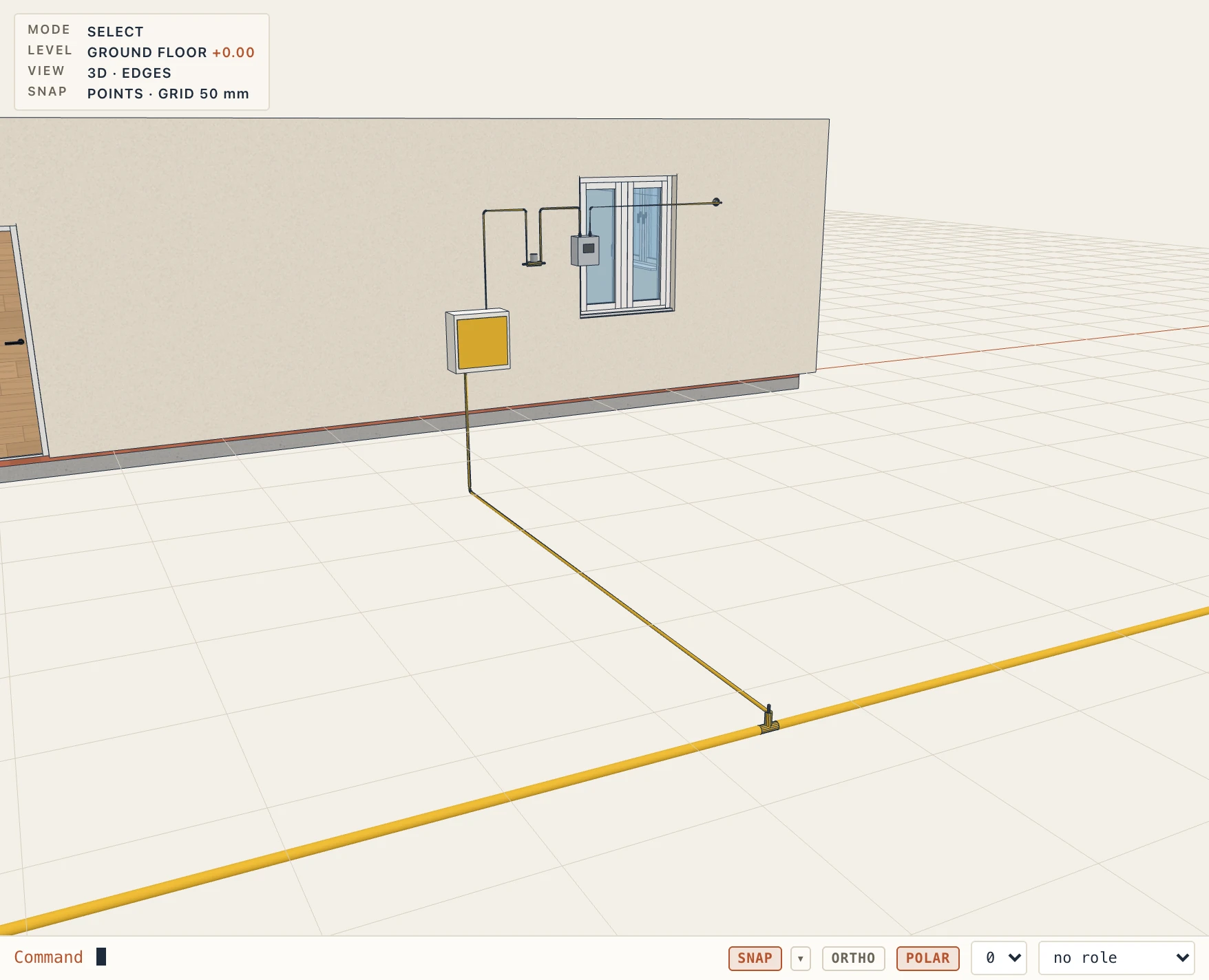
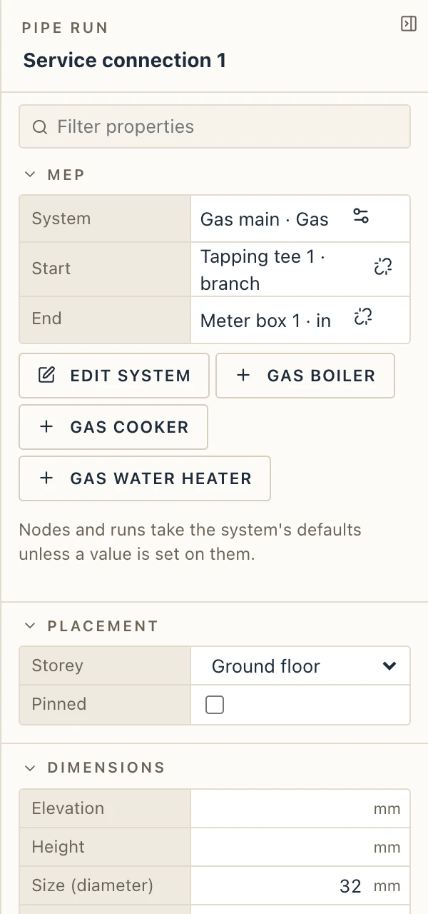
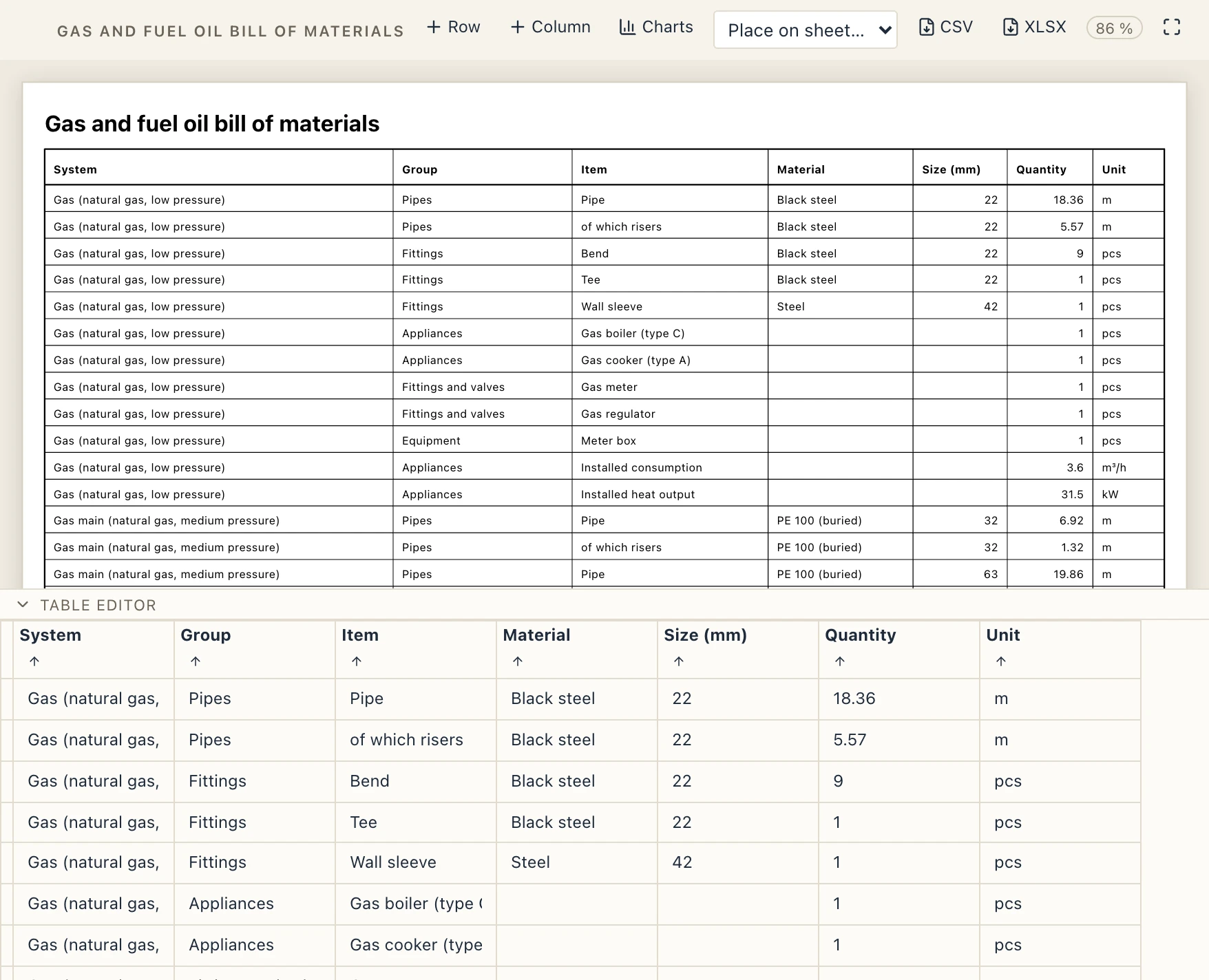
Gas and fuel oil bill of materials under System → Schedules lists, system by system, the pipes by material and size with their length (and of it the risers), the bends, tees and wall sleeves, the warning tape, the valves, meters and boxes, and the appliances with their installed consumption and heat output. In IFC a gas system is an IfcDistributionSystem of type GAS and a fuel oil one FUEL; the meter box is an IfcDistributionChamberElement, the meter an IfcFlowMeter GASMETER, the valves IfcValve, the cooker an IfcBurner, the tank an IfcTank.
Sizing the pipes from the appliances' consumption and checking the pressure drop are engineering, in the Lapin MEP edition.
Fire protection
Fire alarm and Fire hydrants are services of their own under New system, their devices put down with Place node, and the loop closed with Close the loop in the Runs group.
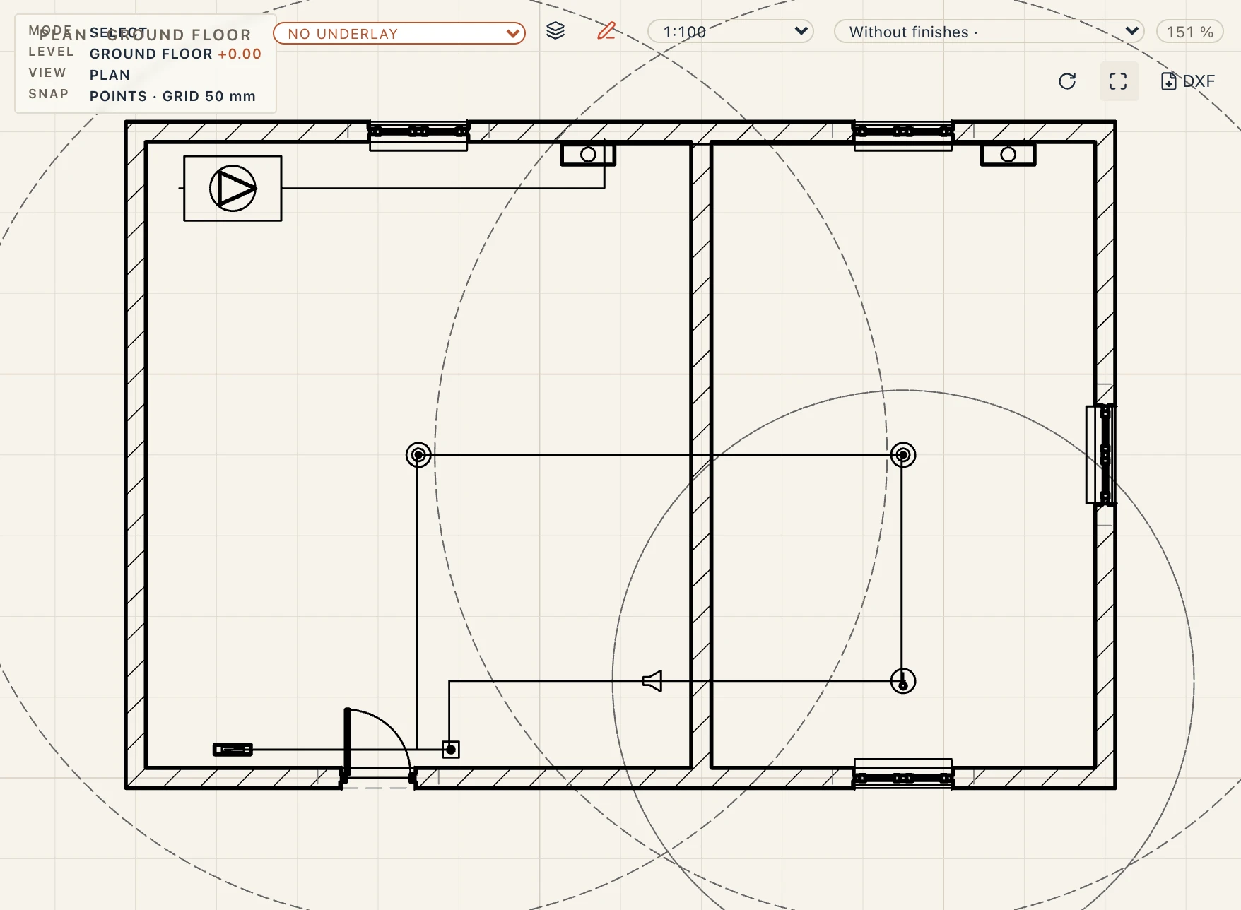
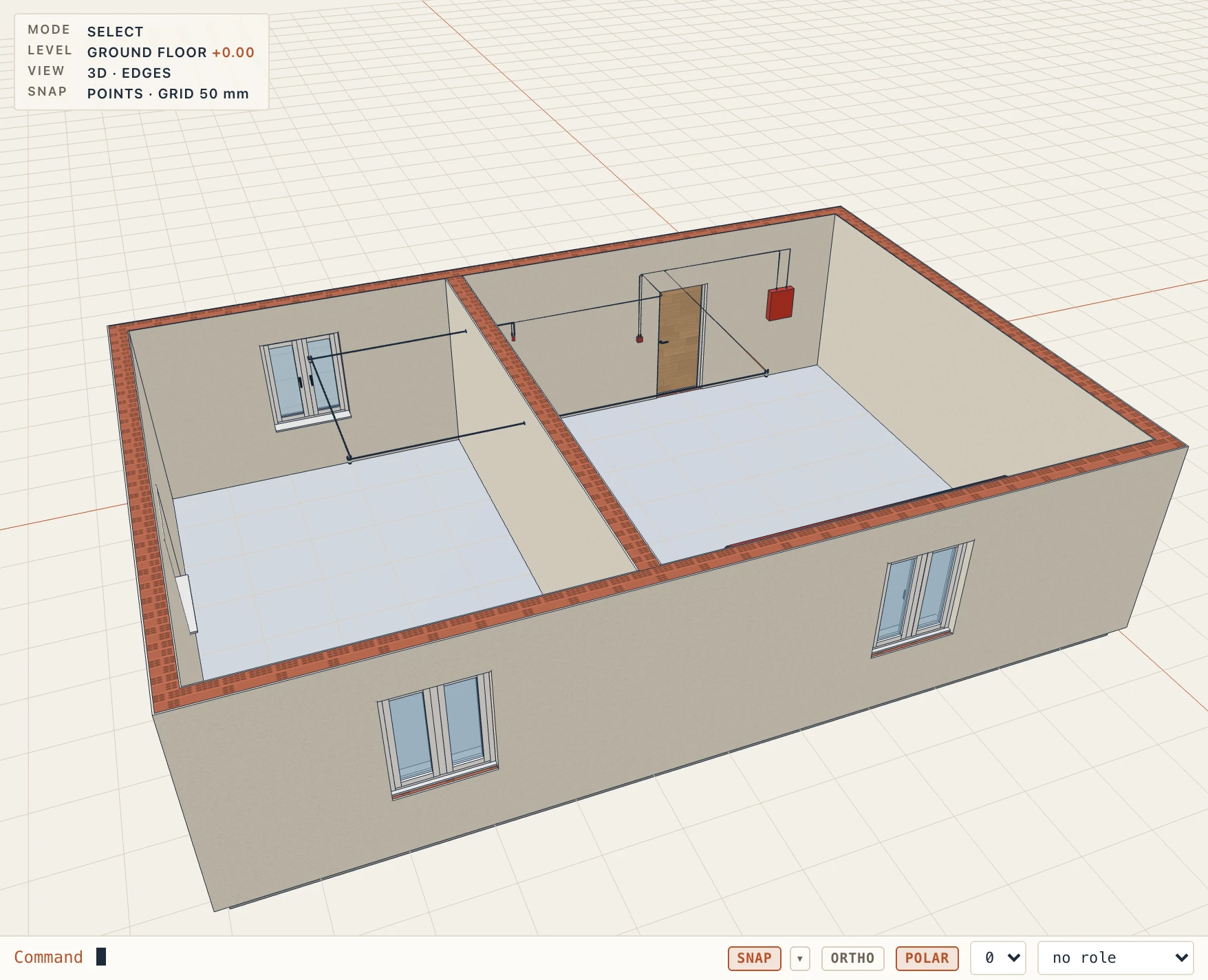
New system → Fire alarm places the fire alarm control panel where you click and a first smoke detector beside it, joined by the loop's cable. Every device you place after that (Smoke detector SD, Heat detector HD, Manual call point MC, Sounder, Sounder beacon) joins the loop's open end, the device placed before it. The cable runs from one device to the next in the order you place them. Close the loop brings the cable from the last device back to the panel's return, so the loop is fed from both ends. The cable is a fire-resistant cable on the ceiling.
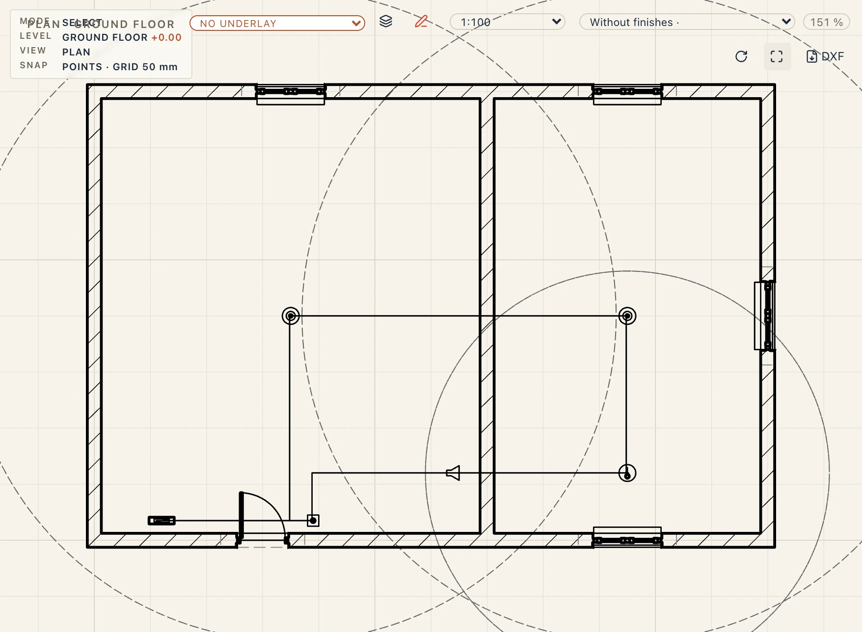
Each detector shows its coverage as a dashed circle. By default the radius comes from the planning table for a flat ceiling up to 6 m: 5.8 m for a smoke detector, 3.6 m for a heat detector. Set a detector's own Coverage radius in its properties when the room, its height or its ceiling asks for another value.
New system → Fire hydrants places a fire pump set and a first internal hydrant joined to it by a galvanised steel pipe (DN 50 by default). Each hydrant placed after it tees onto the network. The fire water reserve feeds the pump by the pump's own suction port, and the fire brigade inlet is joined by hand with Run. External hydrant and Sprinkler complete the network. An internal hydrant draws its reach as a dashed circle: its Hose length (20 m by default) plus its Compact jet (6 m). Set both as the norm asks for the building.
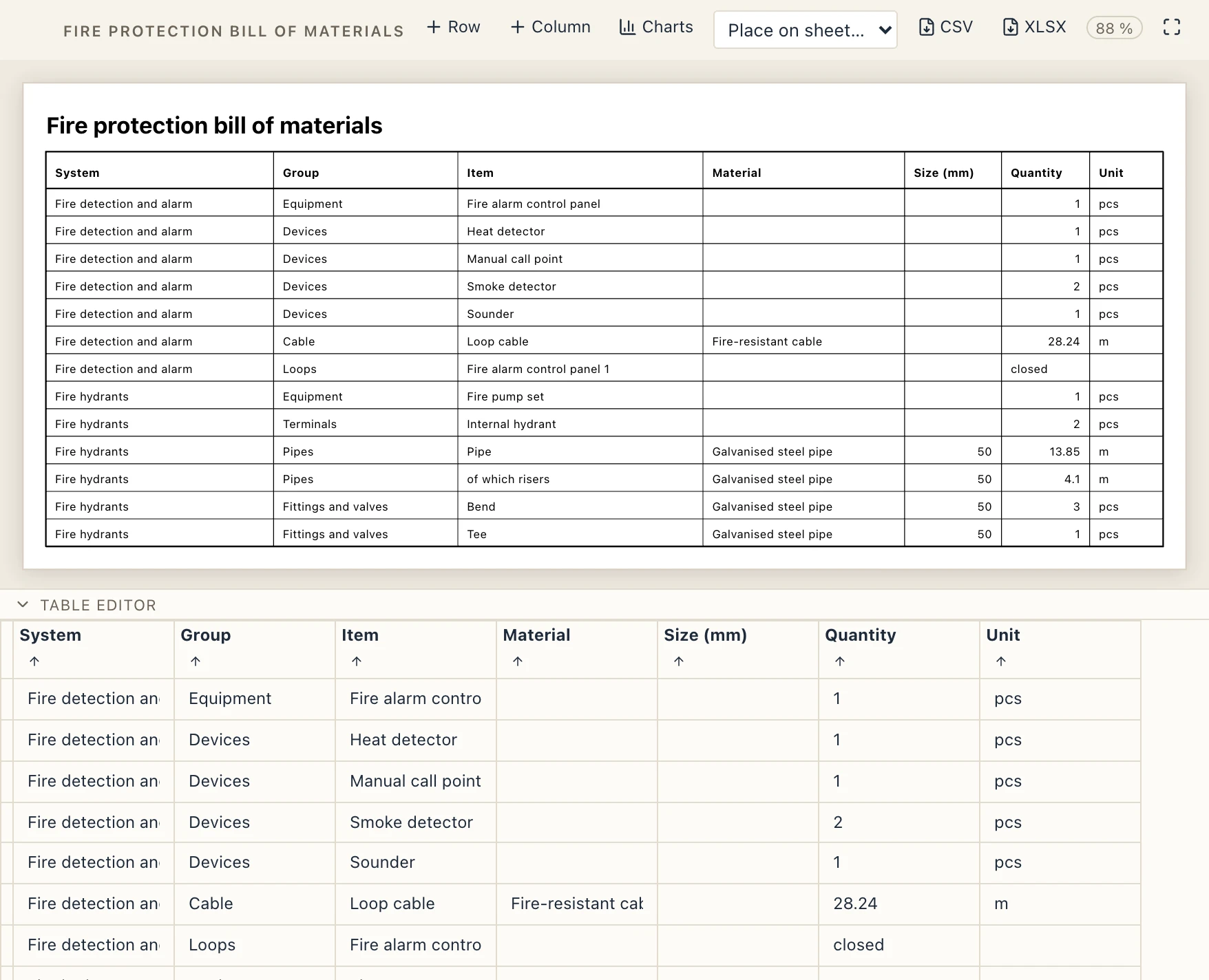
Fire protection bill of materials under System → Schedules lists, system by system:
- the panels, detectors, call points and sounders;
- the loop's cable with its length, and whether each loop is closed;
- the reserve, the pump sets, the hydrants and the sprinklers;
- the pipes by material and size, with their bends and tees.
In IFC both systems are of type FIREPROTECTION. The panel is an IfcUnitaryControlElement ALARMPANEL, the detectors IfcSensor (SMOKESENSOR, HEATSENSOR), the call points and sounders IfcAlarm, the hydrants and sprinklers IfcFireSuppressionTerminal, and the loop's cable IfcCableSegment.
Placing the detectors room by room from the planning table and checking that every room is covered by detectors and hydrants are engineering, in the Lapin MEP edition.
Exhaust fans
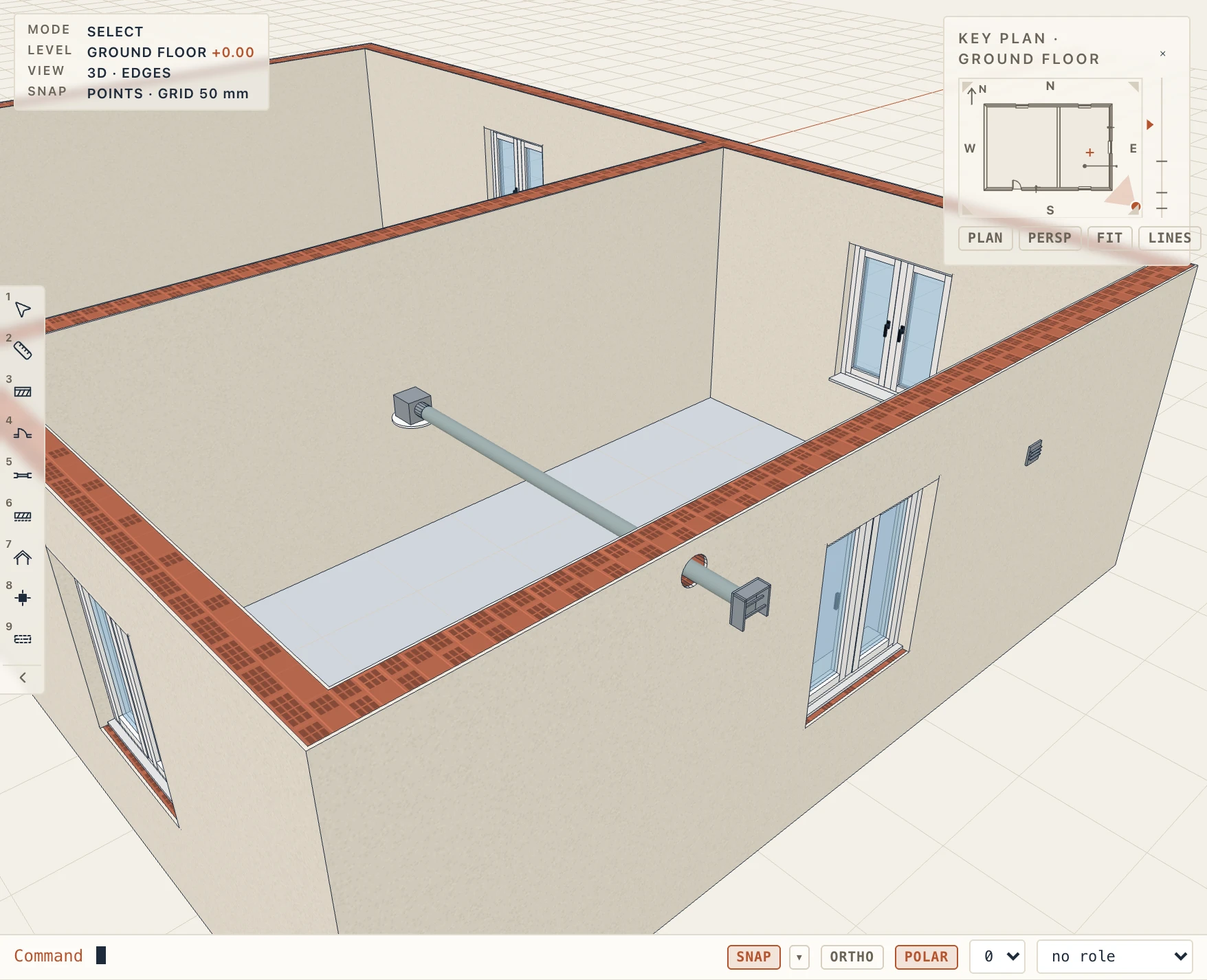
Fans (in the Carriers and fans group of the MEP tab) places bathroom and kitchen extract fans as elements of their own, each of a type you configure:
- Wall fan (VF): an axial fan on a wall, blowing straight out through it;
- Ceiling fan: a fan under the ceiling with a duct out of its side;
- Inline duct fan: a tube fan in the ceiling void, on the duct;
- Window fan: a fan set in a window's glazing;
- Ceiling fan with light: a ceiling fan with a light in its grille;
- Fan with louvre panel: a wall panel with louvres beside the fan and a cover under it.
Choose a tool and click. A wall, window or louvre panel fan goes on the face of the wall nearest the click (within 600 mm), its front to the room, its middle 2.1 m above the floor (a window fan 1.9 m). A ceiling fan goes where you click, under the room's ceiling; an inline fan 250 mm above it. The command line's bar chooses the type the tool puts down, from the project's types or Lapin's built-in ones (a wall fan Ø100 with a humidity sensor, a ceiling fan with a light and a motion sensor, an inline fan for two bathrooms…).
A wall fan cuts a round opening through its wall, 20 mm wider than its duct: the wall's provision, as an MEP run's (it shows as an opening void in plans and goes into IFC as an opening of the wall). It is found by where the fan stands, so a fan moved along the wall takes its opening with it. A window fan sits in the glazing and cuts nothing.
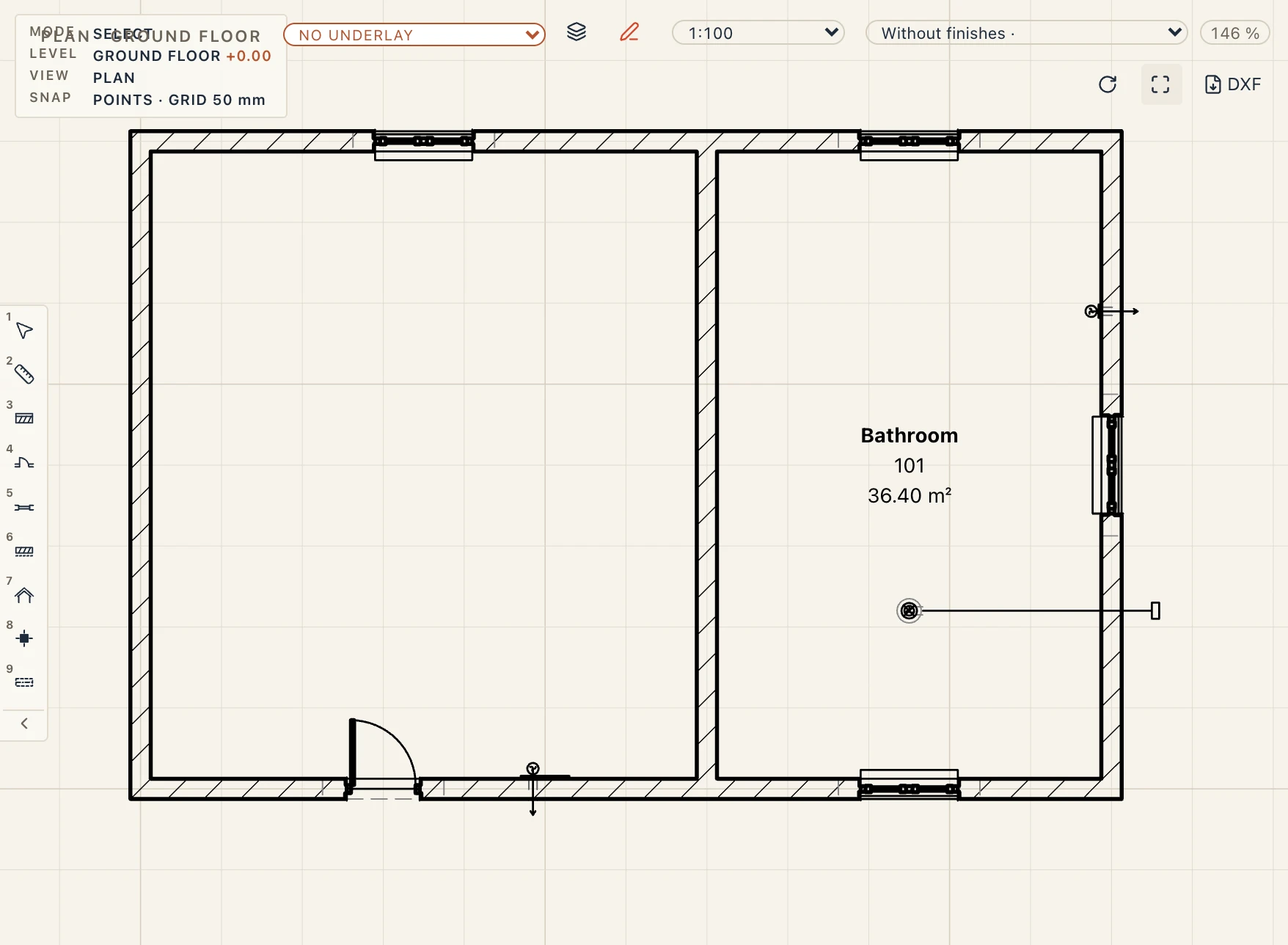
Plans draw a fan by its MEP symbol: a circle with its blades, its face on the wall, its sleeve dashed through the wall and an arrow the way the air goes; a ceiling fan's grille dashed, as it is above the cut. Ceiling plans, sections, elevations and 3D draw the bodies.
Duct to outlet takes a ceiling or inline fan's air out: click the fan, then where the duct goes out. The duct is a run of the project's Bathroom extract system (made with the first duct; it cuts the walls it goes through), as wide as the fan's duct, at the height of its spigot. It ends in a hood on the wall's outside, or, with Through the roof on in the bar, in a pipe rising to a cowl. Moved or raised, the fan takes the duct's start with it.
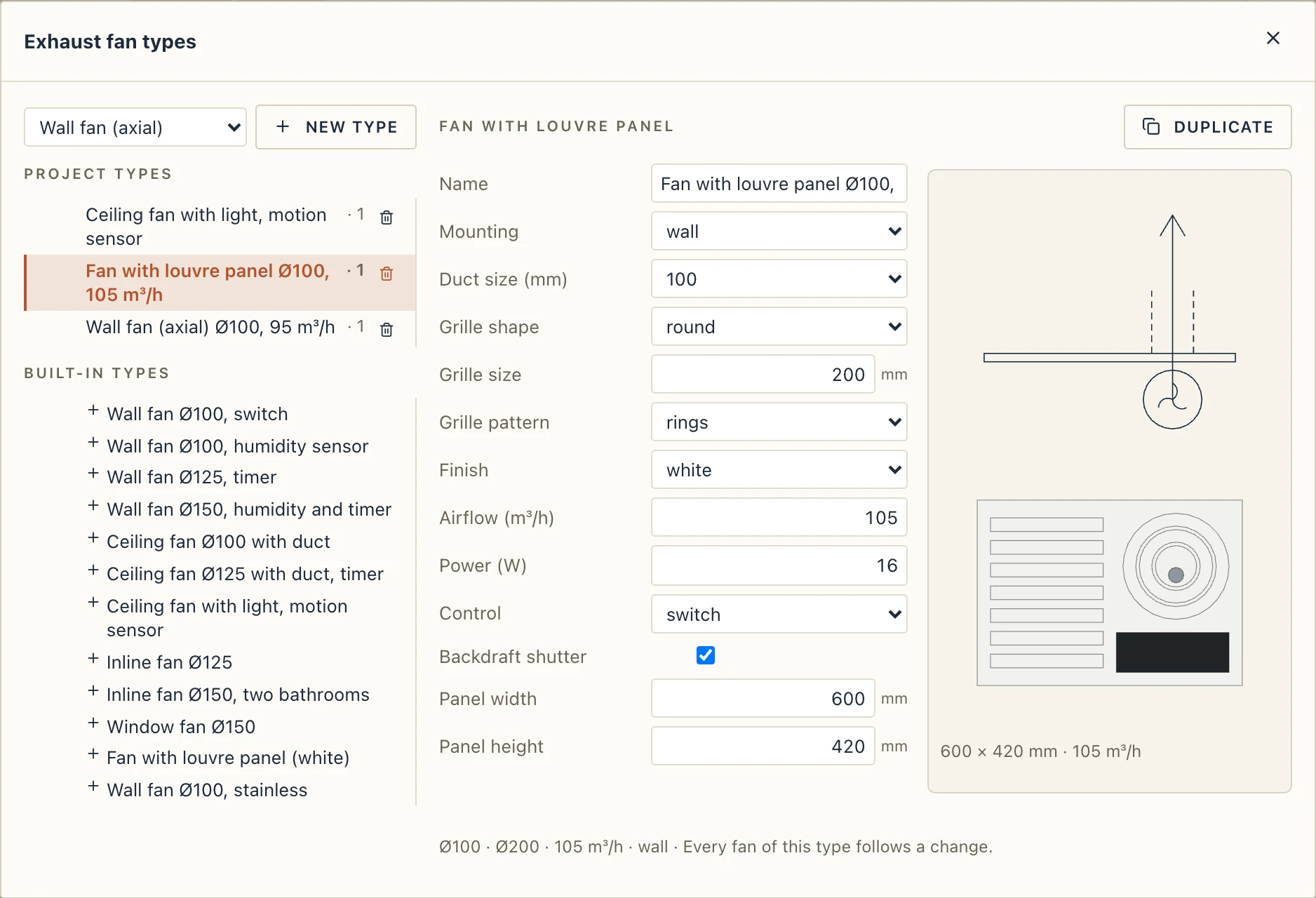
Fan types
Fan types opens the types: the project's, and the built-in ones to add with a click. A type sets:
- its mounting (the ones its kind takes) and its duct size (Ø100, 125, 150 or 200 mm);
- its grille's shape (round or square), size, pattern (louvres, slots, rings or plain) and finish (white, silver, black, stainless or chrome);
- its airflow (m³/h) and power (W);
- its control: a switch, a humidity sensor, a timer, both, or a motion sensor;
- a backdraft shutter, and a ceiling fan's light, an inline fan's body length, a louvre panel's width and height, shown only where they apply.
The preview beside them is the engine's: the plan symbol above, the face below. Every fan of a type follows a change.
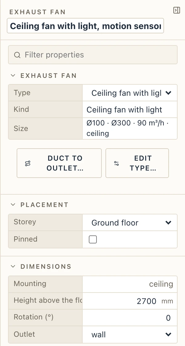
Select a fan to change its type, its height above the floor, its turn and, once it has a duct, its outlet (wall or roof) and how far the outlet rises above the duct. Drag the grip in its middle to move it, the one in front of it to turn it.
Schedules, cost and IFC
The Fan schedule lists every fan with its room, kind, size, airflow, mounting, control, height and outlet, and the total airflow. The Room extract check lists every bathroom, WC and kitchen (and every room with a fan) with its volume, the extract it needs and what its fans give: a bathroom 8 air changes an hour and at least 54 m³/h, a WC 6 and 25 m³/h, a kitchen 6 and 108 m³/h. These are indicative values; check them against the norm you design to.
A new type has the cost article LAP-FAN, counted per fan (Construction → Map articles… changes it).
IFC writes a fan as an IfcFan of an IfcFanType with its predefined type (PROPELLORAXIAL for a wall or window fan, CENTRIFUGALRADIAL for a ceiling fan, TUBEAXIAL for an inline one) and Pset_FanTypeCommon (NominalAirFlowRate, NominalPowerRate); the wall's opening as an IfcOpeningElement. Lapin reads them back as its own fans.
Cable trays and trunking
The Carriers and fans group on the MEP tab draws what cables lie in: cable ladders, perforated and solid trays, trunking (a closed box with its lid) and conduit.
Cable tray (CT) draws a carrier as a run is drawn: click its points on the plan, Enter (or a click on the last point) finishes it. Its legs are laid at 45° steps, so it turns by 45° or 90°. The command line's bar chooses its type and its elevation (2.4 m above the storey by default). The types are the project's own and Lapin's built-in ones, grouped by kind: trays 100×60, 200×60, 300×60 and 400×100, a solid tray 200×60, ladders 300×100 and 600×100, trunking 40×40, 60×40 and 100×60, conduit Ø20, Ø25 and Ø32. The built-in sizes and limits are indicative: check them against the manufacturer's.
An end that lands on another carrier joins it: inside its length a tee (a cross where two meet it across from each other), at its end a reducer when the sizes differ. Each corner is a bend of the type's inside radius. Fittings are worked out from the carriers, never drawn by hand: move a carrier and they follow.
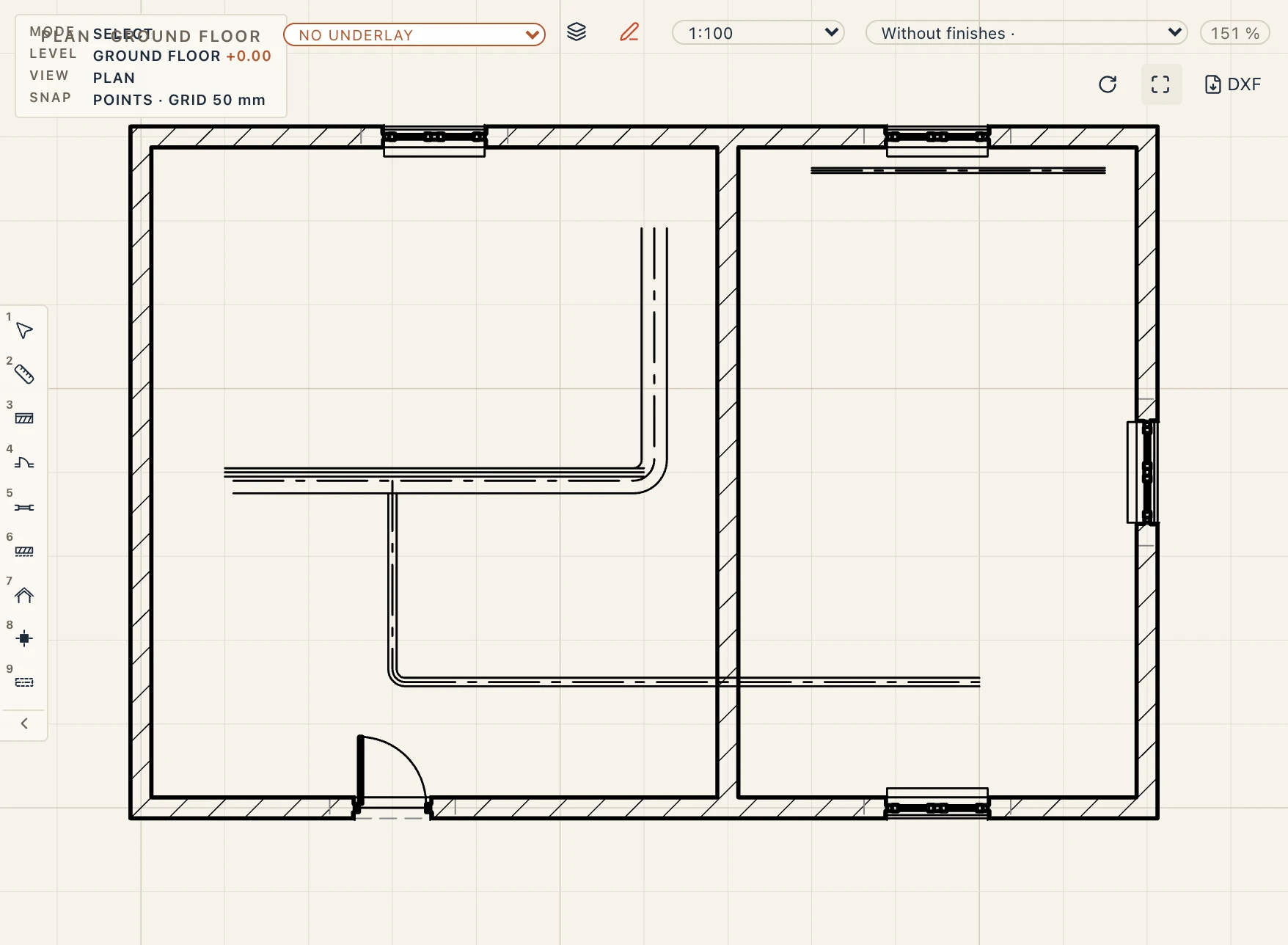
Plans draw a carrier's outline and its dash-dotted centreline; a vertical leg's section crossed. Tags (Annotate → Tag) name its type, as for any element.
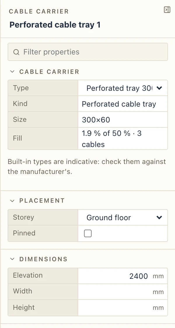
Select a carrier to change its type, its elevation, or a size of its own (Width and Height, a conduit's Diameter); Save size as a type keeps that size as a type of your own. Drag its handles to reshape it. A point can take a level of its own (mep.setCarrierLevels): the carrier goes up or down there in a vertical leg, with a bend each way.
Cables in a carrier. A cable run says which carrier it lies in: choose it under Carrier in the run's properties, or select the cable runs and use Lay in carrier, then click the carrier. The carrier shows its fill: the cables' cross-sections (each run's size is its cable's diameter) over the carrier's usable area, against its type's limit (indicative: 50 % for trays and ladders, 45 % for trunking, 40 % for conduit). A fill over the limit is marked.
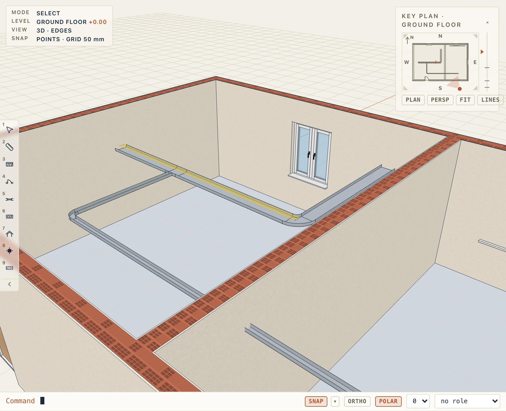
The Cable carriers schedule lists each carrier with its type, kind, size, storey, length, bends, tees, crosses and reducers and its fill, with totals by type. IFC writes a carrier as an IfcCableCarrierSegment (CABLELADDERSEGMENT, CABLETRAYSEGMENT, CABLETRUNKINGSEGMENT or CONDUITSEGMENT) of an IfcCableCarrierSegmentType, its fittings as IfcCableCarrierFittings (BEND, TEE, CROSS, REDUCER) aggregated in it, its ports (CABLECARRIER) and their connections. The clash checks and opening voids see carriers as the other MEP elements.
Coordination: opening voids and clash checks
Every opening in a wall, floor or roof can be a void of its own: a solid as large as the opening, through the whole thickness of its host, finishes included. Clash programs (Navisworks, Solibri, BIMcollab) test MEP against such voids with "completely inside": a pipe, duct or cable tray wholly inside a void passes, one that sticks out of it, or crosses a wall where there is none, is a clash. Lapin runs the same check itself.
Manage → Clash detection → Openings for MEP (one window with the clash tests) runs the check only when asked: nothing runs it by itself, neither an edit nor Manage → Check. Its Settings tab sets what the voids are made for (wall, door, window, floor and roof openings), how much bigger or smaller than their openings they are (Void offset), and the Clearance an MEP element must keep from a void's sides. Run clash check goes once through every pipe, duct and cable carrier — Lapin's runs and the segments of an imported MEP model alike, and an MEP model's own provisions for voids — and keeps what it found as the project's clash report, with the date it ran, until it is run again. When the model changes after that, the report says it is out of date. Its problems are grouped by kind and numbered, each number kept from one run to the next:
- No opening: it goes through the host where there is none;
- Not cut: load-bearing or cut order: no opening, because the runs' own openings (below) do not cut that host;
- Opening too small: it goes through an opening but stands out of it, the clearance included; Short by says by how many millimetres on the worst side;
- Empty void (with Empty voids ticked in Settings): a wall or floor opening nothing goes through (a stairwell is never one).
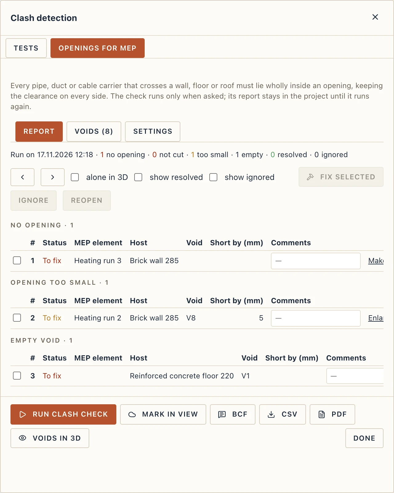
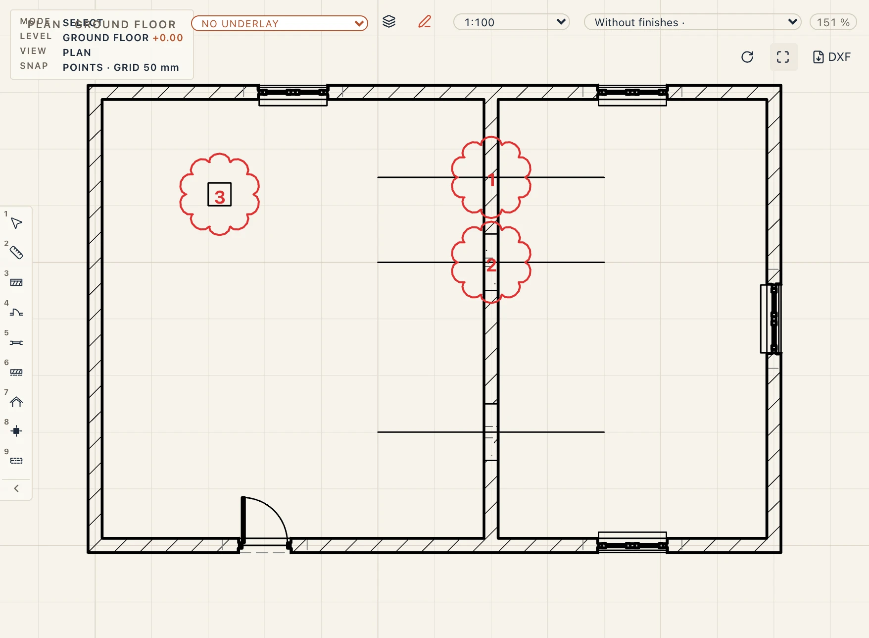
Each problem is To fix, Resolved or Ignored, with a comment. A click on a row shows the pair in 3D, both selected (alone in 3D hides the rest for now); the arrows go to the previous and the next one. Mark in view (also View → Clash marks) draws each open problem in the plan, section or elevation in front as a red cloud with its number, on the screen only.
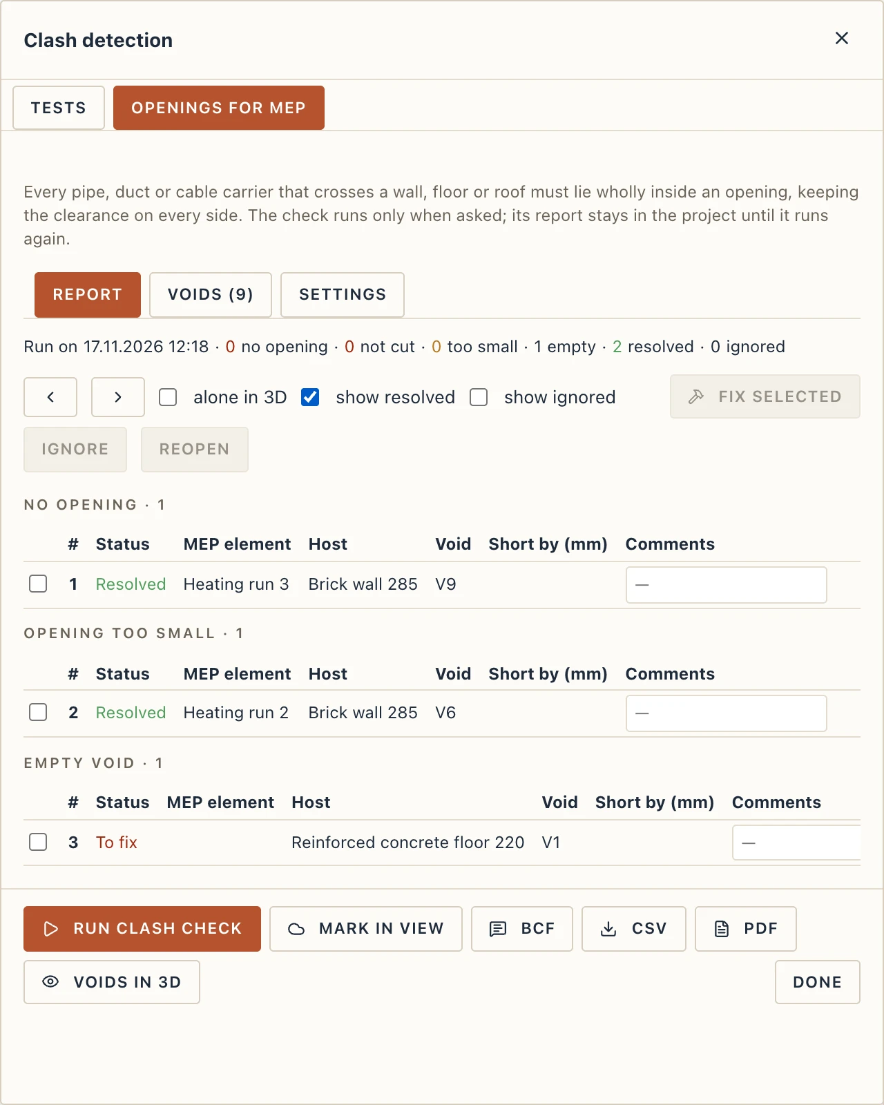
Make opening cuts a bare opening round the element in the wall (round for a pipe or a cable, rectangular for a duct) or in the floor, its sides the clearance away and its size rounded up as the cut order's MEP rule says; Enlarge opening grows the opening that is too small. Fix selected does it for every ticked row, Ignore and Reopen set their status; each is one step to undo. The report then says it is out of date: run it again, and what is fixed is listed Resolved (show resolved). Its line then says at which run it was found resolved and how it is now: the opening it goes through and the run's size in it (Resolved at the run of 04.11.2026 15:20: opening V1 200 mm, run 160 mm.), or that the run no longer goes through; each run after that updates the sizes.
BCF turns the open clashes into remarks of type Clash with their viewpoints (Manage → Model remarks…) and saves them as a BCF file; run again, it updates the same remarks. CSV and PDF save the report as a list. Manage → Check only reads the report: its open clashes are warnings, and so is a report out of date.
Runs that cut their own openings
The cut order (Manage → Cut order) holds MEP runs too, over walls, floors and roofs. With Runs cut walls, floors and roofs on, a run that crosses a wall, a floor or a roof cuts its own opening there: round for a pipe or a cable going square through, rectangular for a duct or a run at a slant, as large as the run's outside (its insulation, a gas pipe's sleeve) and the Clearance round it, rounded up to the step, never under the Smallest opening. The opening is not kept apart: it moves and grows with the run, and goes when the run goes or no longer crosses. It is a void like any opening (drawn, listed, checked), and the IFC export writes it as an IfcOpeningElement with Lapin_ProvisionOpening (and as a provision for void with Opening voids ticked), so a check run again finds nothing to report. A wall, floor or roof that ranks over the runs in the cut order (by its class or its material) is not cut, nor a load-bearing one (LoadBearing in its Pset_…Common) unless cut them too is ticked: the clash check reports them as Not cut. A demolished run cuts nothing, and where a run already passes through an opening none is cut. A system can say otherwise in MEP → Systems… (Runs cut walls, floors and roofs: as the cut order, yes, no). It is on in a new project; a project made before keeps it off until it is switched on.
In a curved wall the opening is found where the run meets the arc, its width measured along it; a rectangular one has radial sides, as a door's or a window's. In a roof it is cut in the slope the run passes through: upright for a pipe standing up (a vent), drawn out along its travel for one at a slant, as in a floor; the purlins and the ridge beam under the slope are not cut, and the clash check reports a run through them. Moving or resizing a run builds again only the walls, floors and roofs it crossed or crosses now, however large the model. Lapin's own IFC read back does not take these openings again when their runs come too (the runs cut them again, never twice); without their run (left out of the import, or a project whose runs cut nothing) each comes in as an opening of its host, so nothing is lost.

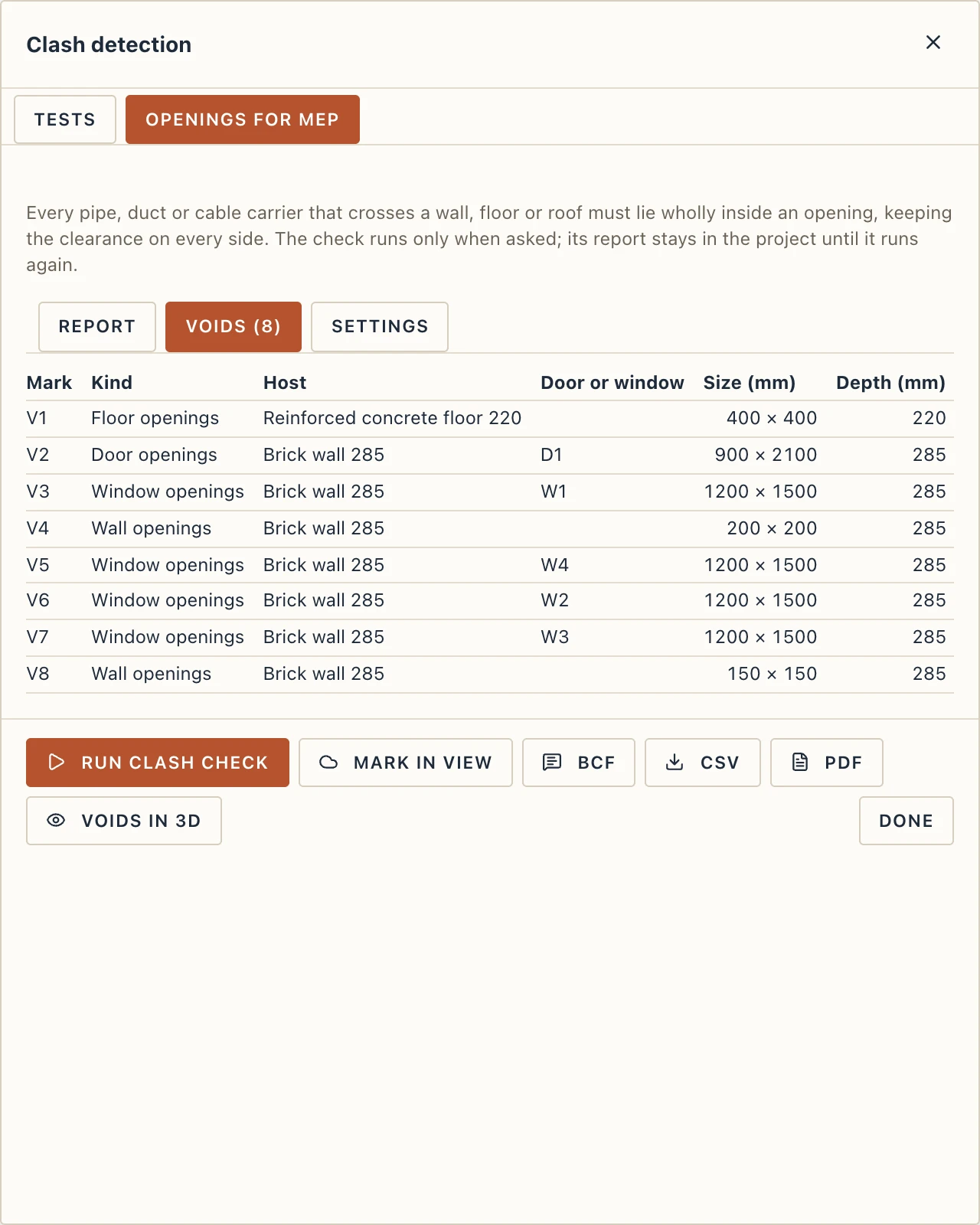
The Voids tab lists every void with its mark (V1, V2… storey by storey), its host, the door or window in it, its size and depth; a click selects its opening.
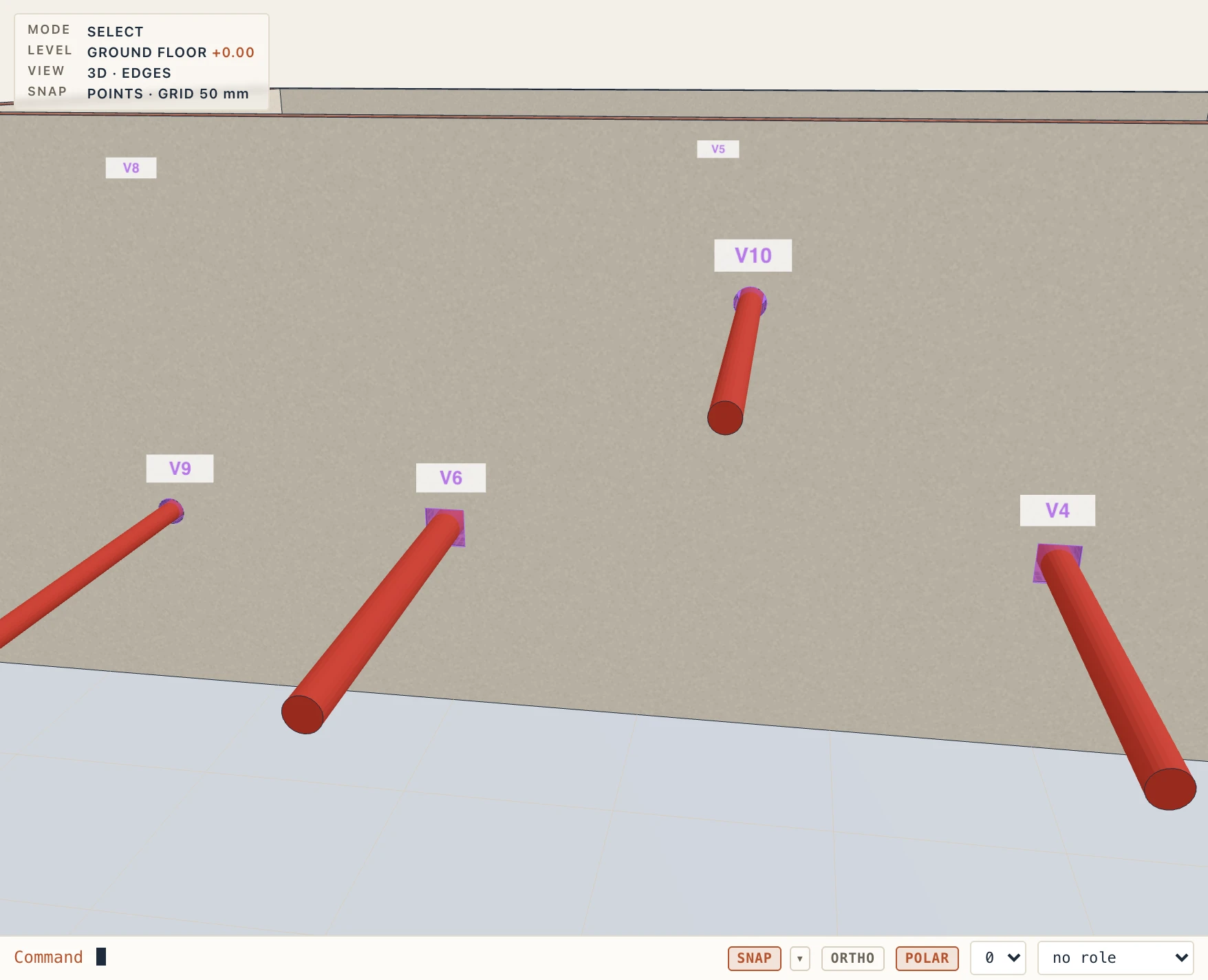
View → Opening voids with the 3D view in front draws them in 3D, translucent violet with their marks; a click on one selects its opening.
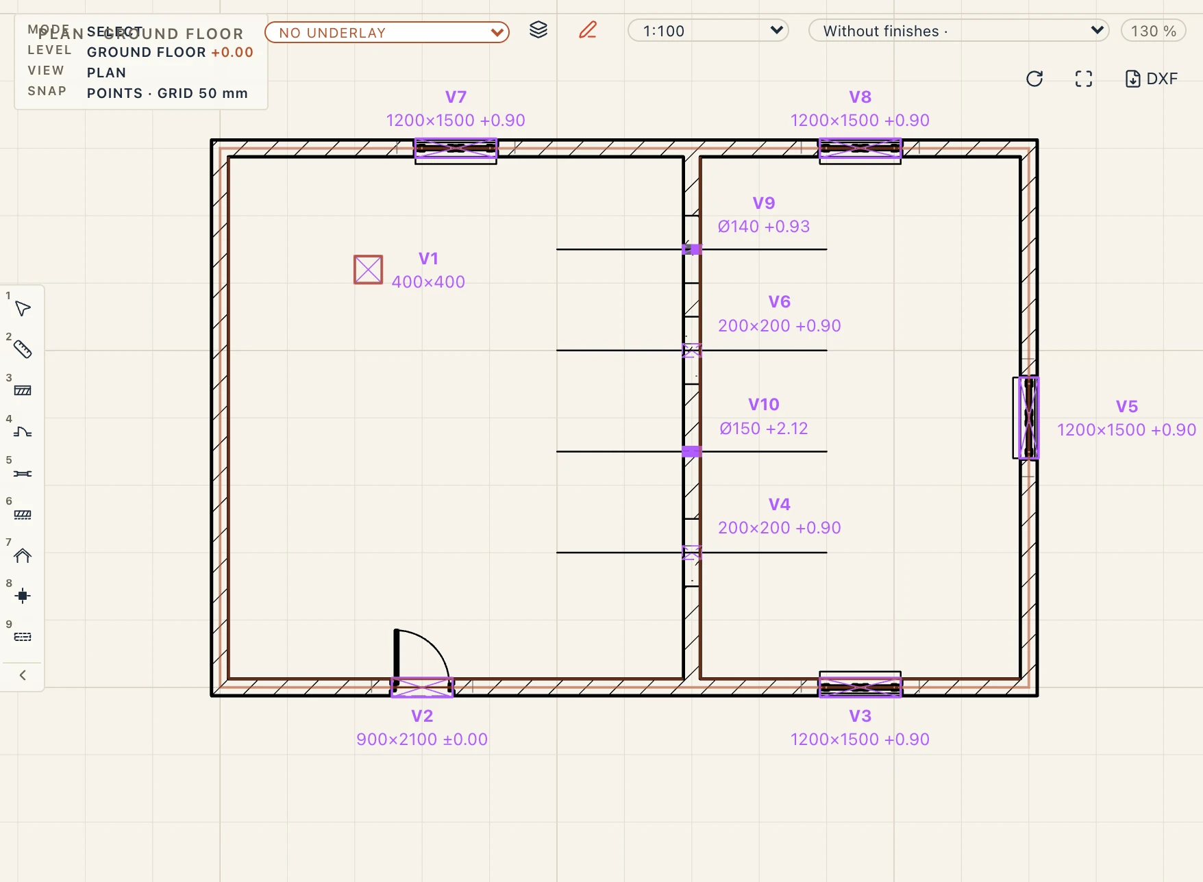
With a plan, section or elevation in front, View → Opening voids draws them in that view instead, as a coordination drawing shows provisions for voids: cut where the view cuts them (a wall's opening through the wall's thickness, a floor's through the slab), seen where it sees them (a floor opening below the plan's cut, a wall's opening on the face an elevation looks at), dashed when a wall's opening lies under the cut or a floor's above it; each crossed corner to corner, with its mark and, under it, its size and a wall opening's bottom level (400×200 +0.90, Ø200). The engine draws them with the rest of the drawing, so sheets, the PDF and DXF (layer VOIDS) print them as the screen shows them.
A void's label stands beside it across its wall, clear of what is already drawn there: a door's swing, the door's or window's marker, other labels. Where both sides of the wall are taken it moves along the wall past the opening, else further out.
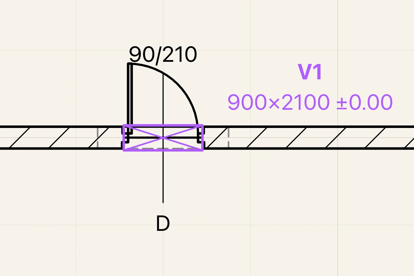
To move a label, click it (or the void): that selects the opening, whose label shows a square grip to move it and a round one to turn it. Ctrl/⌘-click a grip to put the label back where it stands by default, or level again. A moved label is kept by that view, along and across the wall from the void's middle, so it follows the opening when the wall moves; sheets and PDF print it where you put it.
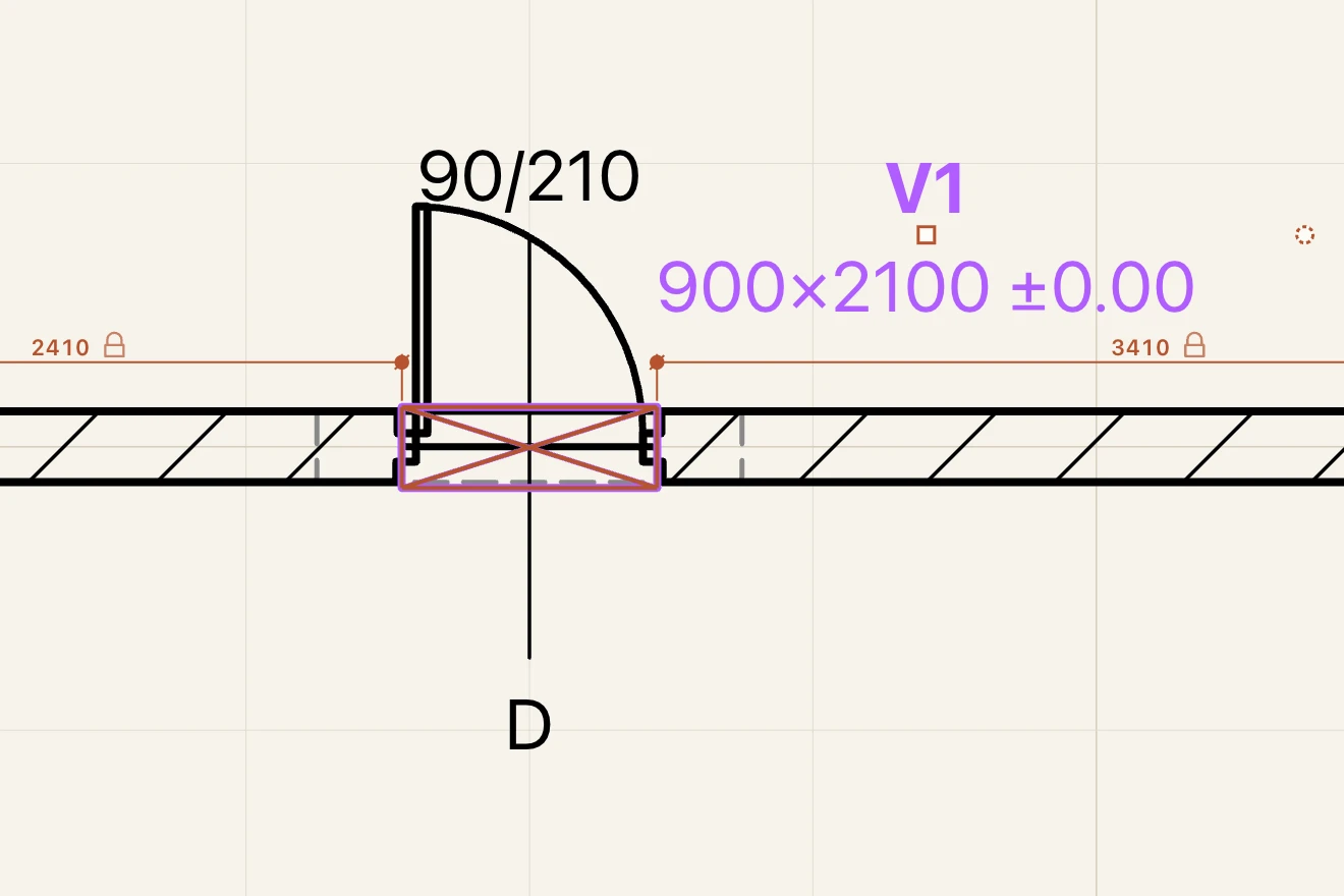
It is a setting of the view, also in its properties (View → View settings): Opening voids, and Void sizes for the size under the mark. Views draw none by default; the Coordination view style (Manage → View styles, chosen as the view's Style) draws them in every view that takes it. Their lines are the Voids category: their pens and colours in Manage → Object styles (cut, projection, hidden, overhead lines), shown or hidden per view in View → Visibility / Graphics….
To hand the voids to a clash program, tick Opening voids in File → Export IFC or Fragments… (or Export 3D…). In IFC each void is an IfcBuildingElementProxy of type PROVISIONFORVOID with Pset_ProvisionForVoid (Shape, Width, Height, Diameter for a round one, Depth) and Lapin's Lapin_OpeningVoid (its mark, kind, host, opening and offset), related to its host; the openings themselves stay IfcOpeningElements as always. Each void keeps its GlobalId from one export to the next, so the clash program follows it. In a mesh export they are a group of their own, Opening voids. Without the box ticked, the exports are as they were.
MEP Pro
The engineering on the network — the demand each run carries and the size that takes it, the checks (open ends, tight bends, drainage falls, overloaded sources), the laying rules by material (copper at 45° steps, PVC turning 45° at most), radiators proposed under windows, routes suggested around the walls, a run's profile and a system's isometric — is in the Lapin MEP edition, which adds the Engineering and Assist groups to this tab.