User guide
Studio
Model free-form solids, sketched on any face or plane, then push, pull, round, hollow, split and repeat them in 3D.
The Studio tab
The Studio tab makes solids that no other tab builds: a bench, a canopy, a handrail, a fountain, a plinth on a facade. Each solid starts from a sketch or a primitive. You then change it in 3D with steps, and every step stays editable.

Its tools stand in six groups: Sketch (lines, rectangles, circles, the Arcs ▾, offset, and under it sketching on a face or a plane, the Sketch edits ▾, the Work planes ▾ and the On face ▾), Constraints (the Geometric ▾ and Dimensions ▾ lists), Solids (extrude, sweep, revolve, loft, edit sketch, the Thick ▾ and Primitives ▾), Parts (placing and editing parts), Modify (push/pull, fillet, chamfer, shell, split, the Arrays ▾ and Move, rotate, mirror ▾) and Boolean. A button with ▾ opens its list; each tool keeps its letters, and Commands… and My tools find it as before.
A Studio solid has an IFC class, like any element. Choose it in its properties: a member, a plate, a covering, a railing, a slab or any other. Its quantities and its export follow that class.
Where you sketch
You sketch a solid's outline with the Draft tools, as closed polylines, rectangles and circles. Lines and arcs that meet end to end also make a closed outline. A closed shape inside the outline is a hole.
You can sketch on four kinds of view:
- A plan draws on its storey's level.
- A section draws on its cut line, upright.
- An elevation or a reference plane: see Reference planes below.
Making a solid
- Extrude (EXTRUDE) pushes the outline straight out. Type S for both ways from the sketch, T for a taper that leans the sides in, and Cut to make it cut the elements you selected before. To run it up to another element's face, use Up to → a face… in its properties, or Extrude up to face. The depth, the heights and the thicknesses are typed in the project's unit, as the prompt says (
Depth (mm):2000is 2 m). - Sweep (SWEEP) runs a profile along a path. TWist turns the section on the way, SCale grows it, and RIse lifts it. A circle that rises becomes a helix, going round TUrns times.
- Loft (LOFT) joins profiles drawn on different views. Type S to make it smooth through them. A line selected with the role rail bends it as a guide.
- Revolve (REVOLVE) turns a profile about an axis line.
- Primitives place a box, cylinder, sphere, cone, torus, wedge or pyramid with one click. Change their sizes and position in their properties.
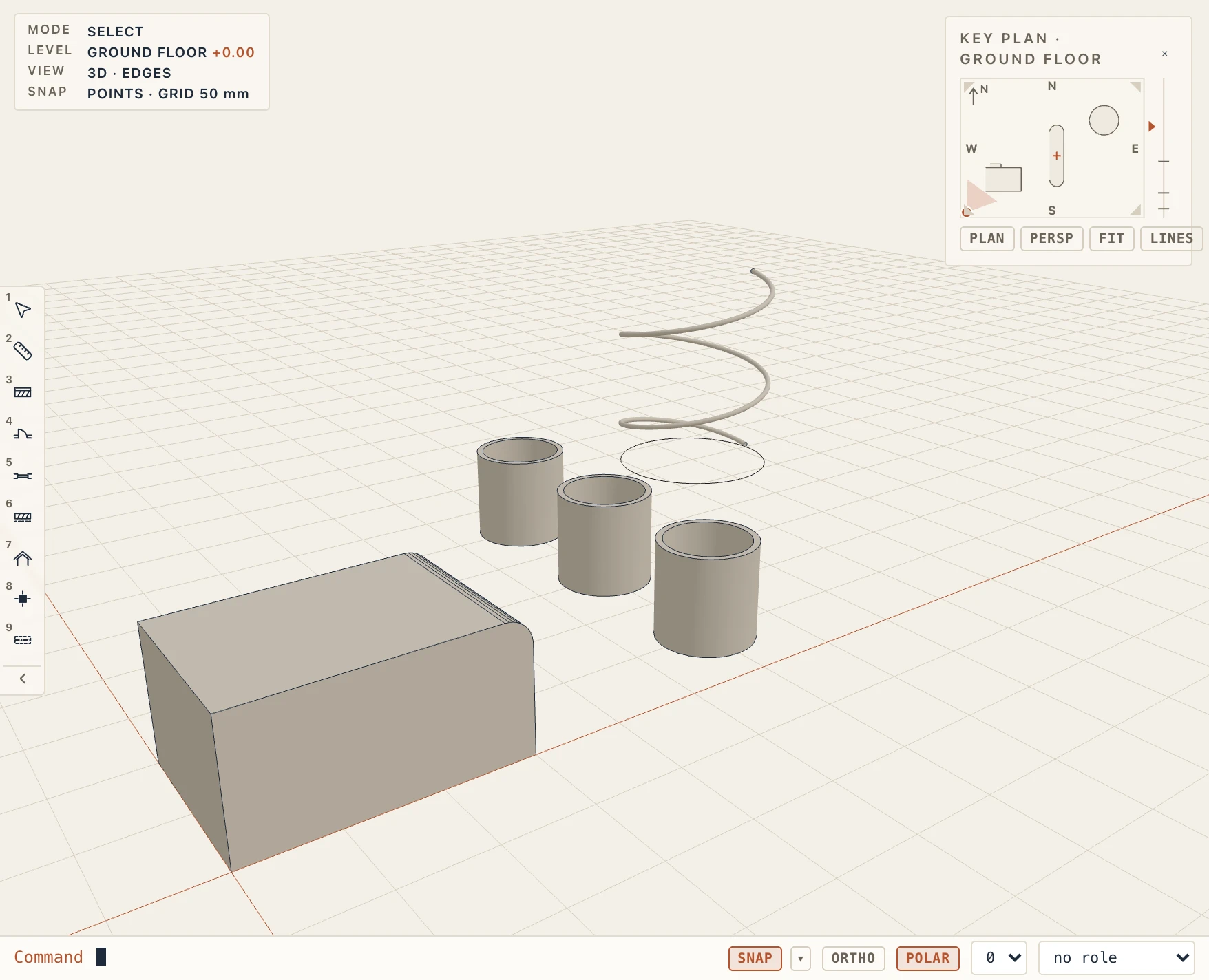
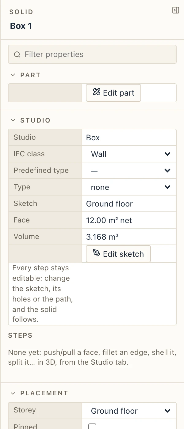
Each solid stays tied to its sketch. Change the shape and the solid follows, with the same GlobalId. Select a solid to change its IFC class, its predefined type and its type in the properties panel. Edit sketch opens the view the sketch lies on.
A solid just made is selected, so it lights up with its sketch's grips. In a plan, a section or an elevation, where the view cuts a solid its cut is filled white: the sketch's lines become a shape you can see is solid. A material with its own fill or hatch draws it in that instead.
Material. Pick a solid's material under Material in the properties panel, from the project's materials, or make a new one with New material…; with several solids selected, it goes to all of them. The material colours the solid in 3D, gives its cut the material's hatch and fill, and is what the quantity takeoff, the cost and the cut order by material go by; the IFC export associates it with the element. A solid type has a Material too: the solids of that type that have none of their own take it, and follow it when it changes. A solid's own material always wins over its type's; choose none to go back to the type's. On a placed part, its own Material is used for all of its bodies; the part type's Material is used for the bodies that have no material in the part's definition.
Ring, Box and Wall strip
These three tools give a drafted shape a thickness in its own plane, then a height away from that plane:
- Ring (RING) takes a circle, an arc or a closed outline and makes a ring or a tube. Its thickness lies inside, outside or centred on the shape.
- Box (BOX) takes a rectangle, a closed polyline or a circle and makes the walls round it. A bottom and a top are optional, each with its own thickness.
- Wall strip (TWALL) takes a line, a polyline or an arc and makes a strip of wall. Its thickness lies left, right or centred, seen walking along the line as you drew it. Its corners are mitred.
Start the tool and click the shape. The command line offers the options as letters: I, O and C (or L, R and C) for where the thickness lies, and for a box B and T to switch the bottom and the top on or off. Then type the thickness and the height, in metres, or press Enter to keep the value shown.
On a plan, the tools make native walls by default, of the wall type chosen in Architecture. A closed shape becomes a loop of walls joined at its corners, a polyline a chain of walls, and an arc or a circle curved walls. Where the thickness lies decides where the walls stand: the wall type's whole thickness goes on the side you chose. A box's bottom and top become floors. Type S before you pick the shape to make a Studio solid instead.
On a section, an elevation or a reference plane, the tools make a Studio solid of the IFC class IfcWall; a box's bottom and top are separate slabs (IfcSlab). The height goes along the plane's normal, towards you; a negative height goes away from you, as with Extrude. To give such a wall a type, select it and pick or make one under Type in the properties panel.
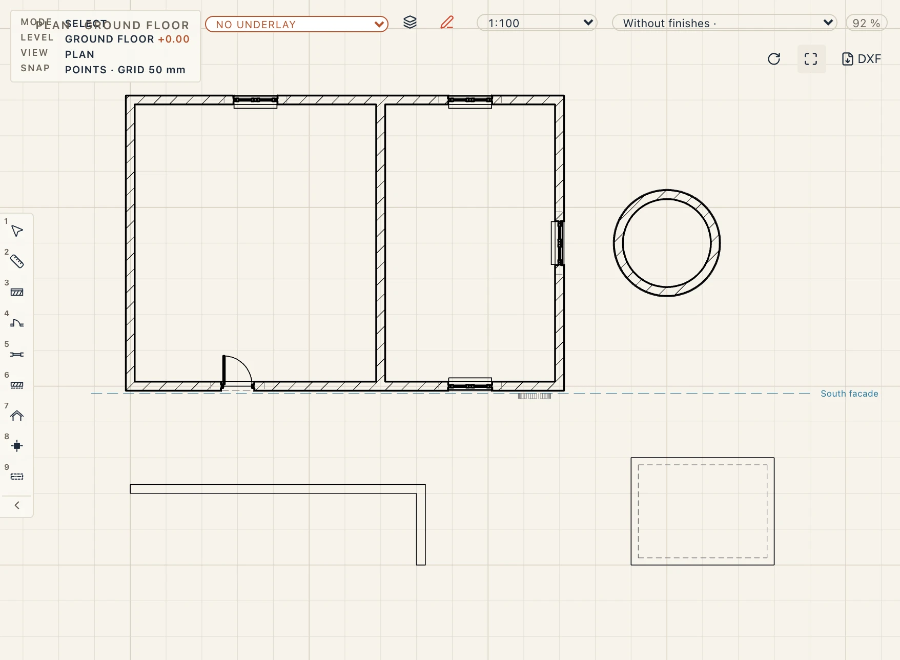
Everything stays parametric. Select the solid and change its Thickness, Height and Thickness lies in the properties panel. For a box, tick Bottom or Top and set their thicknesses: Lapin adds or removes the slabs. A box with a bottom or a top is grouped with them in an assembly (IfcElementAssembly). Drag the shape's grips, or edit it on its view, and the solid is rebuilt.
Reference planes
A reference plane is a plane anywhere in the model with a view of its own. You draw on it with Draft, as on a section, and Studio makes solids on it. Make one from the Studio tab:
- Plane from view (REFPLANE) lies parallel to the plan, section, elevation or plane in front of you. Type how far it is towards you (a negative value goes away).
- Plane on face: in the 3D view, click a face of any element. The plane lies on the face, facing out of it.
- Plane by 3 points: in the 3D view, click three points on the model. The plane passes through them.
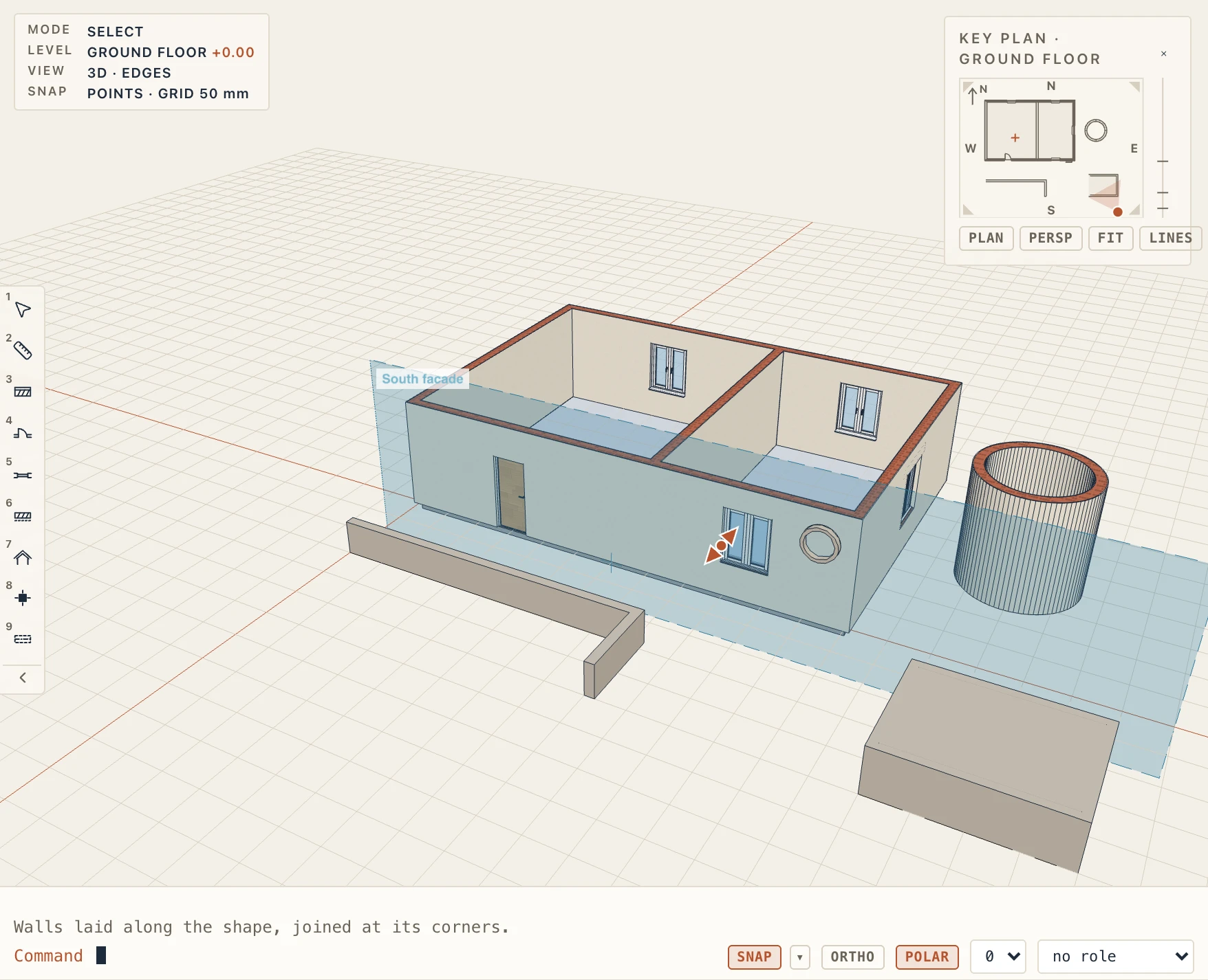
The new plane opens at once. It is listed under Reference planes in the project browser. Its drawing is a section on the plane, looking against the side it faces.
In the 3D view every reference plane is drawn as a translucent pane with its name, as large as the model is on it (or its Drawn width (3D) and Drawn height (3D), 2 × 2 m at least), lit up under the cursor. Click it to select the plane, double-click it to open its view. With the plane selected, drag the arrow at its middle to move it along its normal: the offset reads beside the arrow, and what is drawn on the plane goes with it. View → Reference planes hides and shows the panes; they never go into exports, renders or pictures. In plans, sections and elevations, a plane that cuts the view is drawn as a dashed line with its name, across the view's extent: click it to select the plane, double-click it to open it. A plane parallel to the view is not drawn there (it cuts nothing of it). These lines are for the screen only: sheets never print them.
Select the plane in the browser to move it. Origin x, y and z place it. Faces is the plan direction it faces, Tilt how far it leans back (90° lies flat, facing up) and Spin turns its drawing about its normal. Move along its normal… and Turn about the vertical… do the same in one step. What is drawn on the plane, and every solid made from it, moves with it.
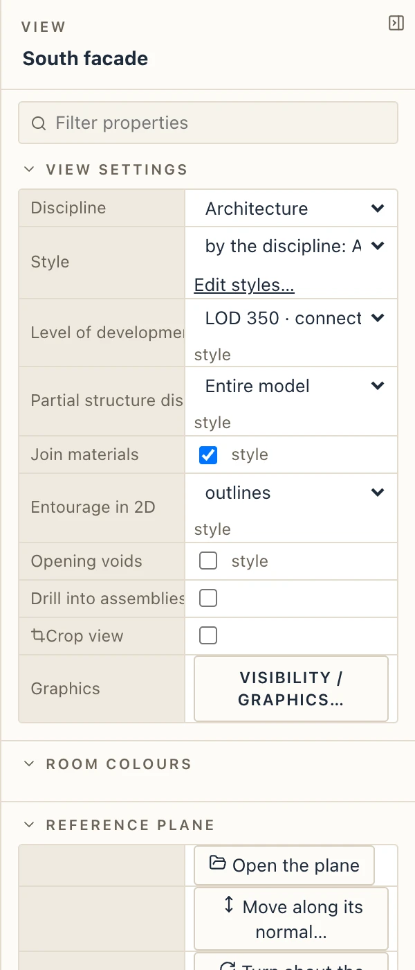
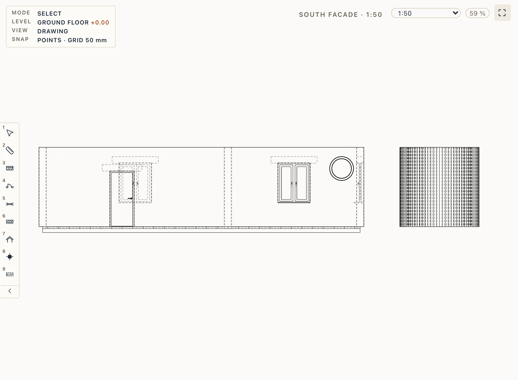
Sections and elevations are planes too. A solid sketched on a section stands on its cut line, and follows the line when you move it. On a developed section, it stands on the piece it is drawn on. An elevation takes a plane of its own the first time you make a solid on it: at the front of the model, with its x as it is drawn now. Change its Sketch plane depth in the elevation's properties to move the plane, and its solids, along the view.
In IFC, a ring, a box's walls and a wall strip are IfcWall elements, a box's bottom and top IfcSlab elements, and a box with them an IfcElementAssembly with IfcRelAggregates; their types are written as IfcWallType and IfcSlabType. Every 3D export (IFC, Fragments, glTF, USD, COLLADA) writes a Studio solid where it stands in the model, whichever plane it was sketched on, with its holes; an assembly is a group node over its parts. Opening Lapin's own IFC again brings the solids back as references, in place, under their class, type and assembly, but no longer editable (their sketches are not in the file). The history of each solid is kept in Lapin's own property set, Lapin_Intent. Studio solids take simple types only, without layers: that is the loose modelling they are for; walls with layers are Lapin's native walls.
Changing a solid in 3D
These tools work on the faces and edges of the body as it is built now. The face under the mouse lights up.
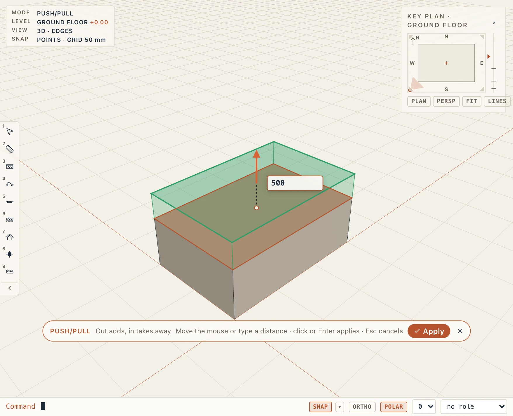
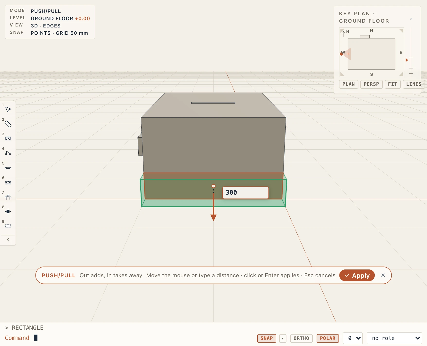
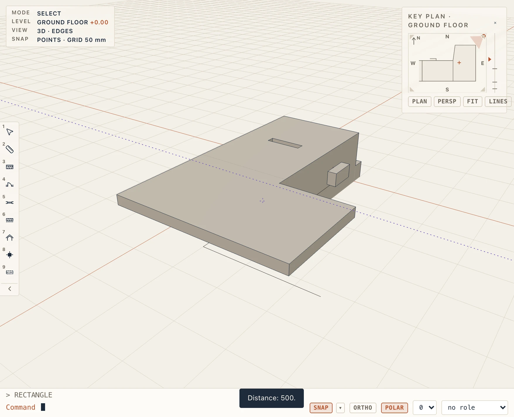
Push/Pull, Split, Slice and Move 3D are handled on the model itself. Click a face, and an arrow stands on it: the mouse moves the face along the arrow, and what the step will make is drawn as you go. Push/pull draws in green what it adds and in red what it takes away; a split or a slice draws its plane in yellow. The distance reads beside the arrow. Type a value to set it exactly, such as 500 or -250. Click or press Enter to apply it, or press Esc to drop it; the tool stays on for the next face. Enter with nothing moved or typed repeats the last distance. A drag goes by the centimetre, or by 10 cm with Shift. The right and the middle button still turn and move the view. The other tools ask for their value in a small box beside the cursor.
- Push/Pull (PU) moves a face out, or in when the distance is negative. On an extrusion, its end changes the depth and its side moves the sketch's edge under it. On a wall or any other element, pulling adds a solid in the face's material, and pushing cuts into the element.
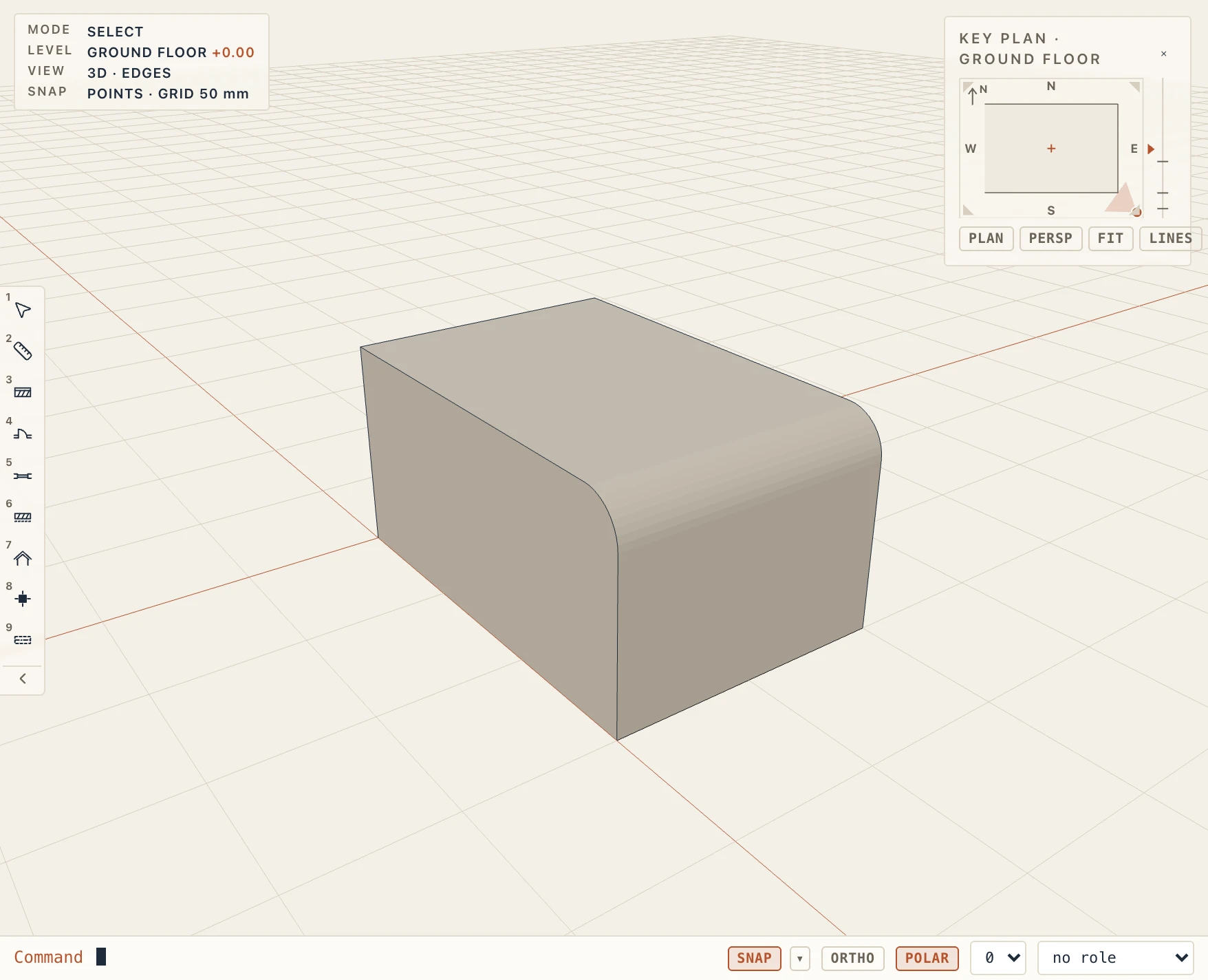
- Fillet edge (FE) rounds the edge nearest your click, and Chamfer edge (CE) bevels it. Choose all round the face to do every edge of the face at once.
- Shell hollows the selected solids, with walls as thick as you type. It can stay closed, or be left open at its end, at its sketch or at both.
- Split cuts a solid in two by a plane parallel to the face you pick, as far into the face as you drag or type. Both parts keep the sketch. Slice keeps one side only: choose Keep behind or Keep in front in the bar at the bottom of the view.
- Array repeats the solid in a row, or in a grid when Rows is more than one (the copies are then its columns, the row step goes from one row to the next), and Polar array repeats it round an upright. With anything else selected (a reference, a group, a wall), they make copies of it instead, as Modify → Array does: In a row, a step along x, y and z, or Round a centre, the angle the copies fill (360° shares a full turn out).
- Rotate 3D turns the solid about an edge you pick. Mirror 3D mirrors it in a face's plane. Move 3D puts arrows along x, y and z on the selection (solids, references, groups or any element): drag one, or type a distance for the axis shown beside the value (Tab goes to the next axis).
Drawing on a face
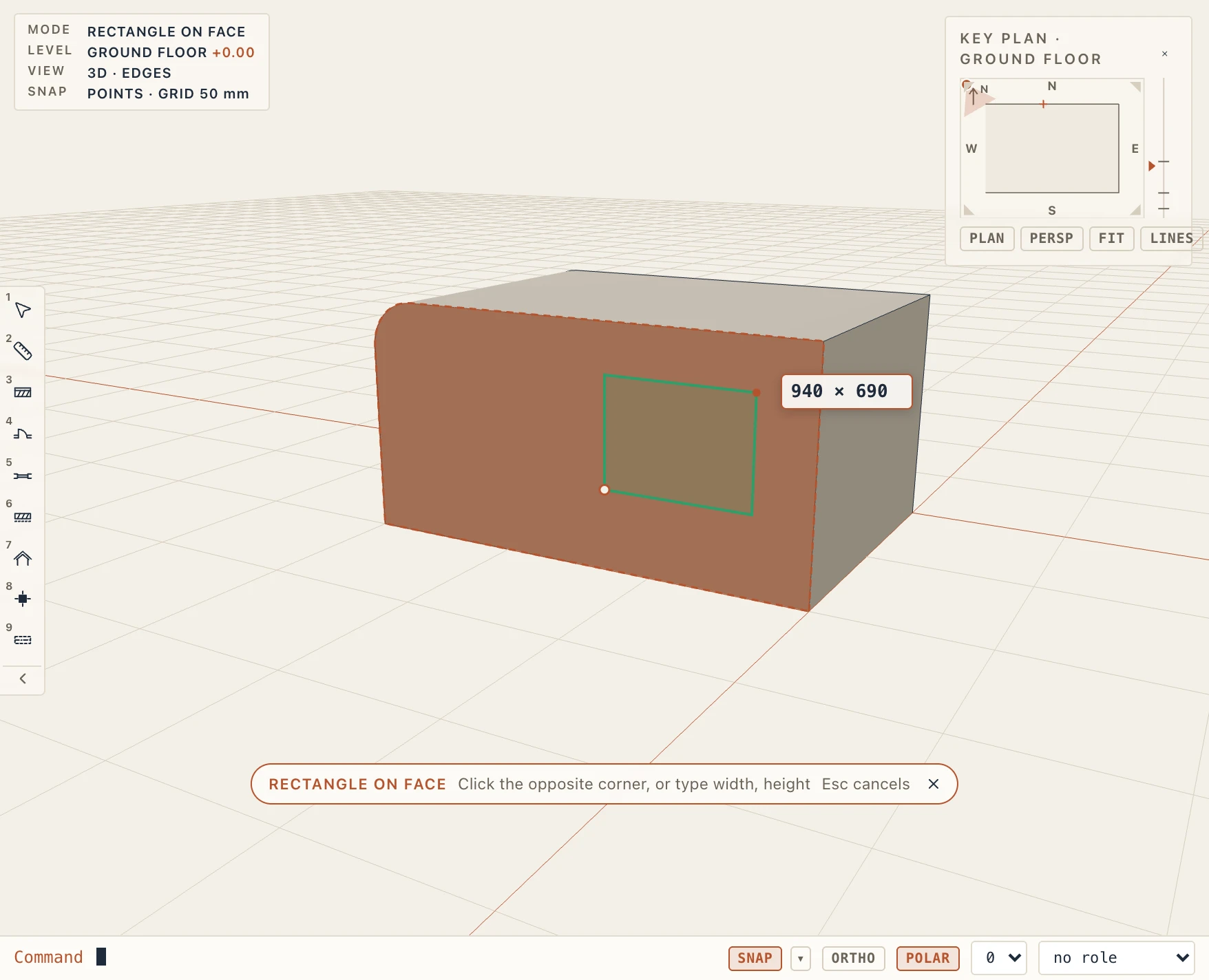
In the 3D view you can draw right on a face and push or pull what you drew. Studio → Sketch → On face ▾ has Rectangle on face (FRE), Circle on face (FCI) and Polygon on face (FPL).
- Click a face of any element: a Studio solid, a wall, a slab or a column. The click is the first point: a rectangle's corner, a circle's centre or a polygon's first corner. The face is outlined while you draw.
- Move the mouse. The shape follows it on the face, with its size beside it. Points snap to the face's corners, the middles of its edges and its middle; otherwise they go by the centimetre, or by 10 cm with Shift. Click the opposite corner, or a point on the circle. You can also type the size: a rectangle's width and height as
1200, 600, or a circle's radius. A polygon takes a click at each corner, or a typed length along the mouse's direction. Click its first corner or press Enter to close it; Backspace takes the last corner back. - As soon as the shape is closed, an arrow stands on it, as with Push/Pull. Pull it out and it becomes a solid standing on the face, in the face's material. Push it in and it becomes a cut into the element: a niche, a pocket, or a hole when it goes right through. Click or press Enter to apply. Esc, or a distance of 0, leaves the shape on the face as a sketch, to extrude later.
The shape is a sketch on a reference plane lying on the face. The plane is named after the element and the face, such as Extrude 1, north face, and shapes drawn on the same face share it. The 3D view doesn't draw these planes, because the face already shows where they are. Open one from the project browser to change the sketch in 2D; the solid or the cut follows it. Push/Pull on the solid's end changes its depth. Push/Pull on a pocket's floor makes the cut deeper or shallower, rather than adding to the element.
Sketching in 3D
The Sketch group of the Studio tab draws lines and shapes right in the 3D view, in two ways that store the same thing: a sketch on the face's reference plane, as above.
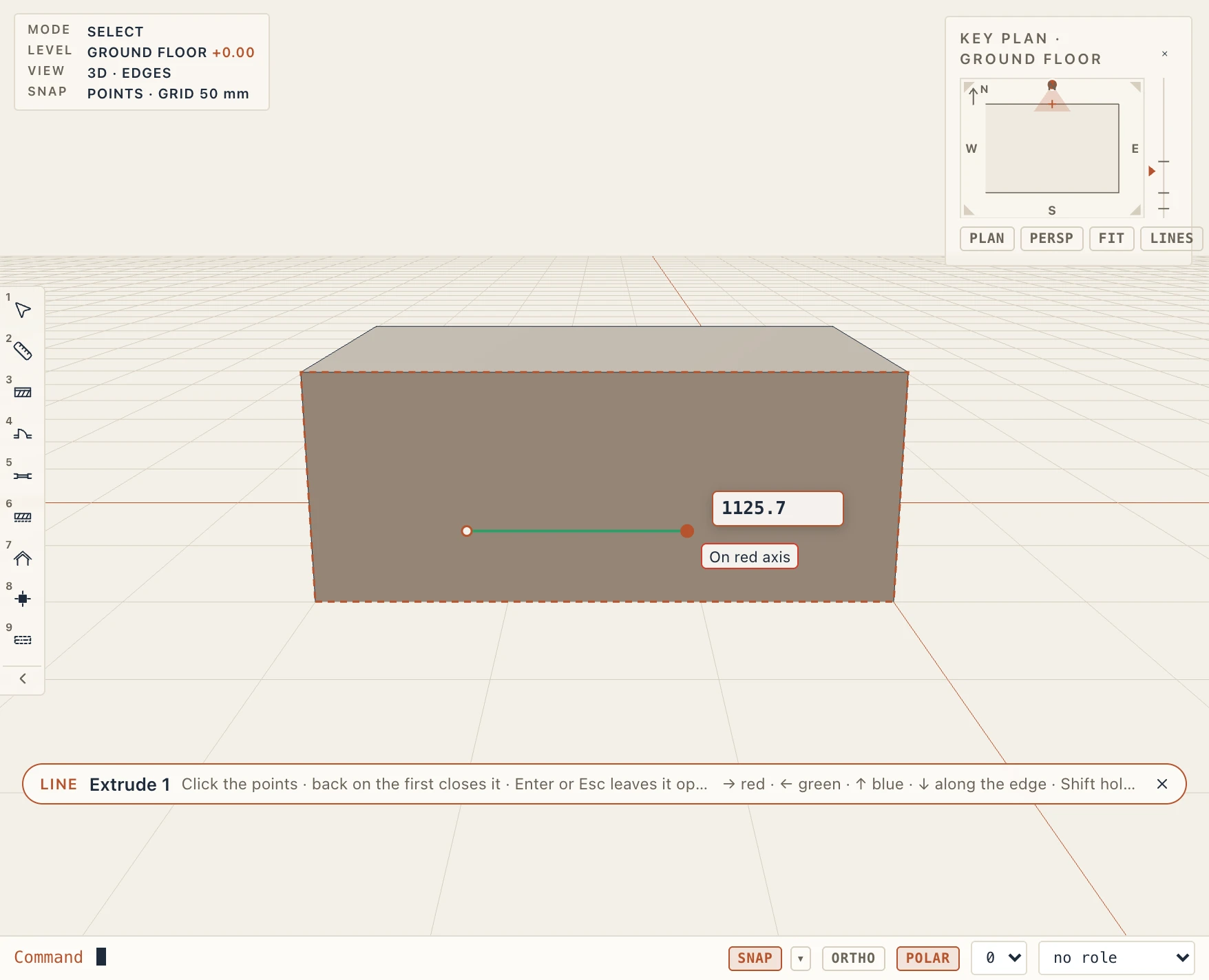
Straight on the face, as in SketchUp. With no sketch open, Line (KL), Rectangle (KR) and Circle (KC) draw on the face under the cursor. The face lights up as you pass over it; in empty space you draw on the active storey's level. The first click fixes the plane.
- The cursor infers what it is on, and says so beside it: Endpoint, Midpoint, On edge, Intersection, On face. From the last point it follows the model's axes that lie on the face, drawn in their colours (red x, green y, blue z), and runs Parallel to edge or Perpendicular to edge in magenta.
- → locks red, ← green, ↑ blue, ↓ the way of the edge last inferred; the same key lets go. Hold Shift to keep the direction inferred now.
- Type a value at any time, without clicking a box, and press Enter:
1200is the next segment's length along the way the mouse points (1000<30at 30°),1200,600a rectangle's width and height,300orr300a circle's radius. - A line goes on point by point. Back on its first point the loop closes and the push/pull arrow stands on it at once; Esc keeps it a sketch. Enter or Esc before that leaves the line open, as a sketch on the face. Backspace takes the last point back. The tool stays on for the next shape; Esc with nothing drawn ends it.
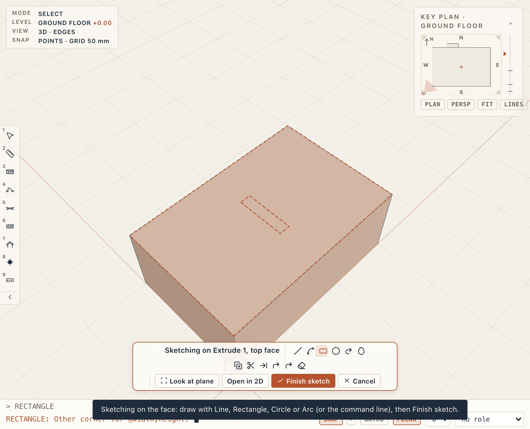
On a work plane, as in CAD. Sketch on face (KF) and a click on a face make that face the active work plane: it is lit, and the sketch bar says Sketching on the face: the same bar as every sketch in Lapin (a floor's Edit sketch, a part's sketch), with Draft's tools (Line, Polyline, Rectangle, Circle, Arc, Ellipse, Offset, Trim, Extend, Fillet, Chamfer, Erase), Finish sketch, Cancel (what you drew since the sketch began goes, in one undo step), Look at plane and Open in 2D (the plane's own view, the same sketch). Sketch on plane does the same with the reference plane you selected. While it is active, Line, Rectangle and Circle start the command line's own LINE, RECTANGLE and CIRCLE on it, and every Draft command you type works on it in the plane's own coordinates, with the object snaps, ortho and tracking of a plan, the face's edges among them. Finish sketch (KE, or Enter with no command running) welds the lines drawn and puts the push/pull arrow on the closed shape drawn last; Esc lets the selection go, then leaves the sketch, and what you drew stays. Look at plane (KP) turns the view square to the plane. On a face, the plane's x runs left to right as you see the face from outside, level, and its y runs up the face (on a top face x is east and y north), so @1500,0 goes to the right and the typed sizes of both ways read the same.
The two arcs each do one thing, sketch or no sketch: 2-point arc (KA) is SketchUp's (below), 3-point arc runs the command line's ARC through three points, on the work plane when one is active, else on the storey's level.
Lines split faces. A line drawn across a face, from edge to edge (or a closed loop of lines and arcs inside it), splits it into regions. The face lights up region by region under the cursor, and Push/Pull on a region pushes or pulls that region alone: a solid of its own on the face, or a cut into it. Lines that stop short of an edge split nothing. A closed loop drawn inside a face (or a region) is a hole of it, as in SketchUp: Push/Pull on the face round it leaves the loop out, and the loop is pushed or pulled on its own. The outline of a region pushed or pulled is kept as the solid's sketch on the face's plane, where you edit it (from that plane's view or the project browser); the 3D view does not draw it, so nothing is left hanging over a part pushed away. The lines you drew stay drawn.
- 2-point arc (KA) draws on the face under the cursor, SketchUp's way: click the start, the end, then how far it bulges (or type the chord's length, then the bulge).
- Offset (KO) clicks a face, or a region of it, and draws its outline again inward or outward through the cursor, or by the distance you type; the closed shape gets the push/pull arrow at once.
- With a sketch open, Offset, Trim, Extend and Fillet run the command line's own OFFSET, TRIM, EXTEND and FILLET on the work plane.
- A shape drafted on a reference plane, selected in the 3D view, shows its points there. Drag one: it moves on the plane, snapping as the sketch tools do, and the solid made from the sketch follows.
- Both ways also snap to the edges of other elements lying in the plane, such as a neighbouring block's side flush with the face.
Tape measure, guides and Follow Me.
- Tape measure (KM) measures and leaves guides, as SketchUp's. Click an edge, move away from it and click: a guide line runs parallel to the edge through that point, or at the distance you type. Click a point instead, and the second click shows the distance and leaves a guide point there. Guides are dashed, both ways of sketching snap to them (and to where they cross the face), they are kept with the project, and they are never exported or printed. Erase guides takes them all away.
- Follow Me (FM) sweeps a face along a path where it stands: click the face (or a region of it split by lines), then the path, either a drafted line, polyline, arc or circle, or another face whose edges it follows round, such as a top face for a cornice. Corners are mitred. The face becomes a sketch on its plane and the result is one Studio solid that follows both sketches.
- SketchUp shortcuts switches SketchUp's one-letter keys on in the 3D view, for this computer: L line, R rectangle, C circle, A arc, P push/pull, F offset, T tape measure, M move, E erase, Space select. They are off by default because they would take the place of Lapin's two-letter shortcuts that start with those letters in the 3D view; the two-letter shortcuts and the command line work as before everywhere else.
The steps
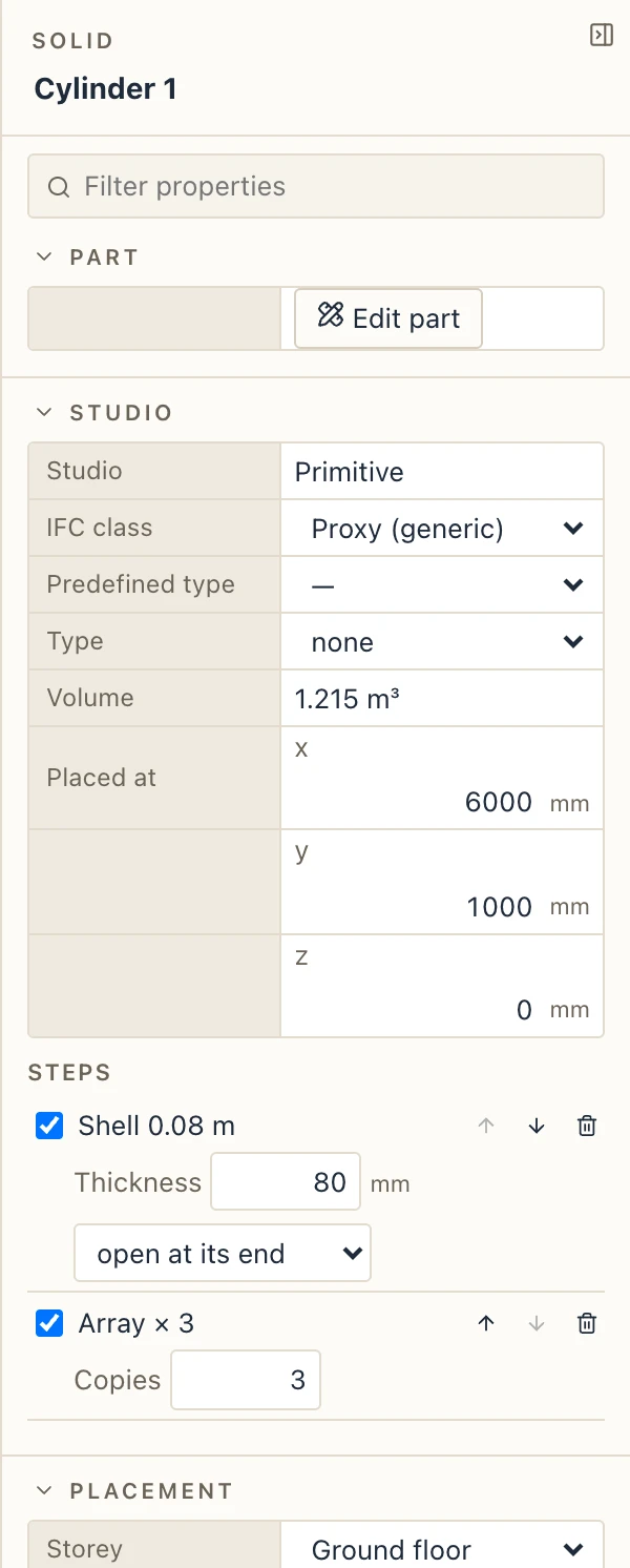
The properties of a Studio solid list its steps in order. Each step can be switched off, moved earlier or later, changed or removed. Change the sketch, and each step is done again on the new body. A step that can no longer find its face or edge says so under Problems.
A polyline's properties list its sides. Type a side's length, and its end moves along it. The sides after it follow, up to the next side that runs the same way, so a rectangle stays a rectangle. A solid drawn on it follows too.
Meshes from other programs
File → Import mesh (OBJ, STL, glTF)… brings in a mesh as references you can see and snap to. An OBJ or STL file does not say its unit or which way is up, so Lapin asks. A reference moves, turns, mirrors and is copied as it is, like any element. To change its shape, select it and click Make Studio solid. It then takes push/pull, fillets, booleans and the other steps. The same tool works on walls, slabs and elements from IFC files.
Booleans
Subtract, Union and Intersect combine any elements, with the first one selected as the target. The tools stay editable, and the result follows them. Show operands shows the hidden tools of a union for editing. Remove operation separates the elements again.
Parts and families
A part (what used to be a family) is a solid of your own with parameters, placed as many times as you need, from Studio → Parts…. See the Families page for the manager and the Parts page: select an object of one and press Tab to edit it in place.
Parts
Select a solid or a placed part in 3D and press Tab, double-click it, or use Studio → Parts → Edit part: the rest of the model fades and the part's tree lists its origin, sketches, steps and parameters. See the Parts page.