User guide
Simple rebar
Reinforcement drawn on sections and plans, bars along an element's edges, your own bar shapes, cross-sections cut where you click, the bar bending schedule by your standard and BVBS.
The Simple rebar tab draws reinforcement the way a bar list is made: bars as shapes with their dimensions, stirrups spread along a beam, marks in balloons, and a schedule that sums them up. It works on any view: a section, a plan, an elevation.

A section where you work
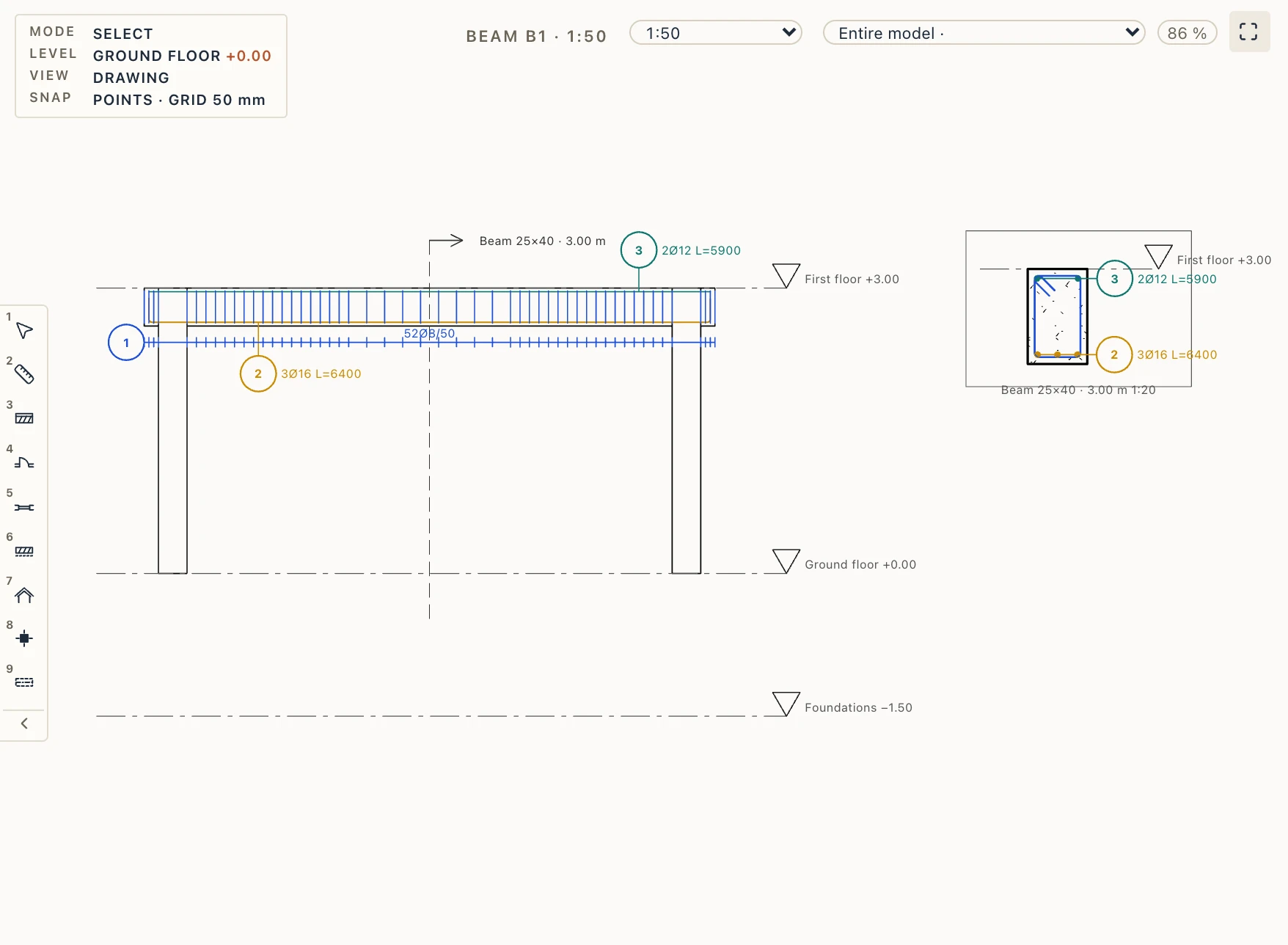
Reinforcement needs the cross-section beside the longitudinal one. Section here does both: pick a beam, a column or a wall in the view you are in, and where you click a section is cut across it, perpendicular to its axis, and drawn beside your click, in the same view, with half a metre of what surrounds it (the slab, the column). A column is cut horizontally at the height you clicked. Click inside the element's cut, not only on its edge: in a section or an elevation, as in a plan, the click takes the element whose cut holds it.
The inset view follows the element: move the beam and the section moves with it. Drag the inset by its grip; its properties give it a scale factor and a frame. Section across makes the same section as a view of its own, and Inset view puts any existing view into the one you are in, at real size and the host's scale, so the bars you draw over it fit its concrete. Inset views are not only rebar's: View → Inset view works in any plan, section or elevation, with a scale and a crop of its own (see Inset views).
Bars
Straight bar, L bar, U bar, Stirrup, Tie and Polyline bar are placed with a click (the polyline by its vertices). Each is a shape with parameters: drag a grip and the dimension it stands for follows; type it in the properties panel in millimetres. The bars are drawn as thick as they are, in a colour for each diameter (Rebar settings), and bent at the radius SR EN 1992-1-1 asks: a mandrel of 4Ø up to Ø16, 7Ø over.
Hooks are set on each end: 90°, 135° or 180°, their straight length by practice (12Ø, 10Ø, 5Ø, never under 50 mm), on the other side when asked. A stirrup is born with two 135° hooks turned inside.
Anchor grips. A selected bar seen from the front shows, beside its grips, orange diamonds standing outside it by the cover: one at its origin and one at each free end (an end with a hook has none). They stand for the formwork face: drag one onto the element's cut — its corner, its face; the drawing snaps there — and the bar stops the cover inside it. The end's anchor sets the bar's length, the origin's moves the whole bar. The cover is the bar's own, typed in the Cover field of its properties (clear it to go back), else the stirrup cover of its host's type plus the stirrup, else the one in Rebar settings; the field says which as a hint.
Bar in section is a bar seen end on: a dot of its diameter, with the length it has along the bar. Same bar in section puts the selected bar as a dot elsewhere, without counting it twice. An Array in the properties repeats a bar every so many millimetres, as the bars of a row in a cross-section.
The mark's balloon shows the mark number and what the bar is: 4Ø12 L=2450. Drag the balloon where it reads best.
The label's style says what it writes and where it stands: its parts in order (count, diameter, step, length, mark, steel, free text), the balloon, whether the text runs horizontal, along the bars or at an angle, the side of the bars it stands on and how far off them, the leader. It is set in Rebar settings for each kind (bars, stirrups on the type, column bars, distributions), on a type beside its stirrups, and on a bar in its properties, the most specific winning. A balloon is never drawn without a mark. The labels of a type's stirrups, of a column's bars and of a bar seen in another view have grips too: drag one and it keeps that place on that view (Put the label back in the properties undoes it); until then, labels that would meet stack under one another in the order of their marks.
A distribution — stirrups on a type, stirrups along a path — is marked as a dimension string without values: a line parallel to the bars outside them, a short tick where each bar crosses it and at both ends, the label above the line along it, the balloon touching its start. Drag the balloon where it reads best; drag the string's middle to move it off the bars. Marked by in the label's style turns the string off and leaves the text and balloon beside the bars. The leader may be none, one line, or a line to each bar seen as a dot (the default for bars in a cross-section: one bar, one line; over sixteen, only the ends and the middle one). Drag the middle of a leader to bend it there; the elbow then has its own grip, and Ctrl/⌘-click on it takes it away.
Lengths are the nominal ones, measured on the bar's axis between its corners, hooks included; the developed length round the bends is told in the properties panel.
Split bar cuts a longitudinal bar that is longer than the stock it is delivered in (12 m, or 6 m, in Rebar settings). Where the two pieces overlap is your decision, not Lapin's: a bottom bar laps near the supports, a top bar away from them. So you give the lap zone yourself: click the bar at one end of the lap, then at the other; or click where the first bar ends and type the lap length (800 for 800 mm), measured along the bar; Enter or Escape after the first click ends the settings' lap length (50Ø unless set) at that click. In the bar's properties the same zone is typed as Lap from … to … in millimetres from the bar's start, with the lap length beside them (changing it keeps to and moves from); the first bar ends at to, the second starts at from, and the two lengths are shown while you type, before Split the bar. The first keeps the bar's mark and start hook, the second gets the next mark and the end hook, and the schedule counts them as two marks with their own lengths. The second piece is drawn a hair beside the first so the lap reads. A bar over the stock length is warned of in its properties, with Cut at the stock length ending the lap at the stock length, so the first piece is exactly that long.
Bar shapes of your own
The shapes in the Bars group are the Eurocode's. A firm that follows another standard (BS 8666, ISO 4066, a German or an American one) or has its own list of shape codes makes them in Simple rebar → Bar shapes…. The dialog lists This project's shapes (with how many bars use each) and Lapin's own, and has New, Import… and Export….
A shape has:
- a Code, as your standard names it (21, 11, 41…), a Name and the Standard it belongs to;
- Parameters: a key (A, B, C…), a label, a Default and a Least, in the project's length unit;
- Legs: each leg's Length, which is a parameter's key (
A) or a formula (A - 2 * R1), and the Turn in degrees, counter-clockwise, from that leg to the next (the last has none); - an optional hook at each end: 90°, 135° or 180°.
The Preview beside them is the engine's own drawing of the shape, redrawn as you type. If the definition cannot be read (a key that is not a parameter, a turn the engine cannot bend), it says why in red and Save waits. Add to the project (or Save) keeps it; Delete takes it away, and the bars of it keep their own copy.
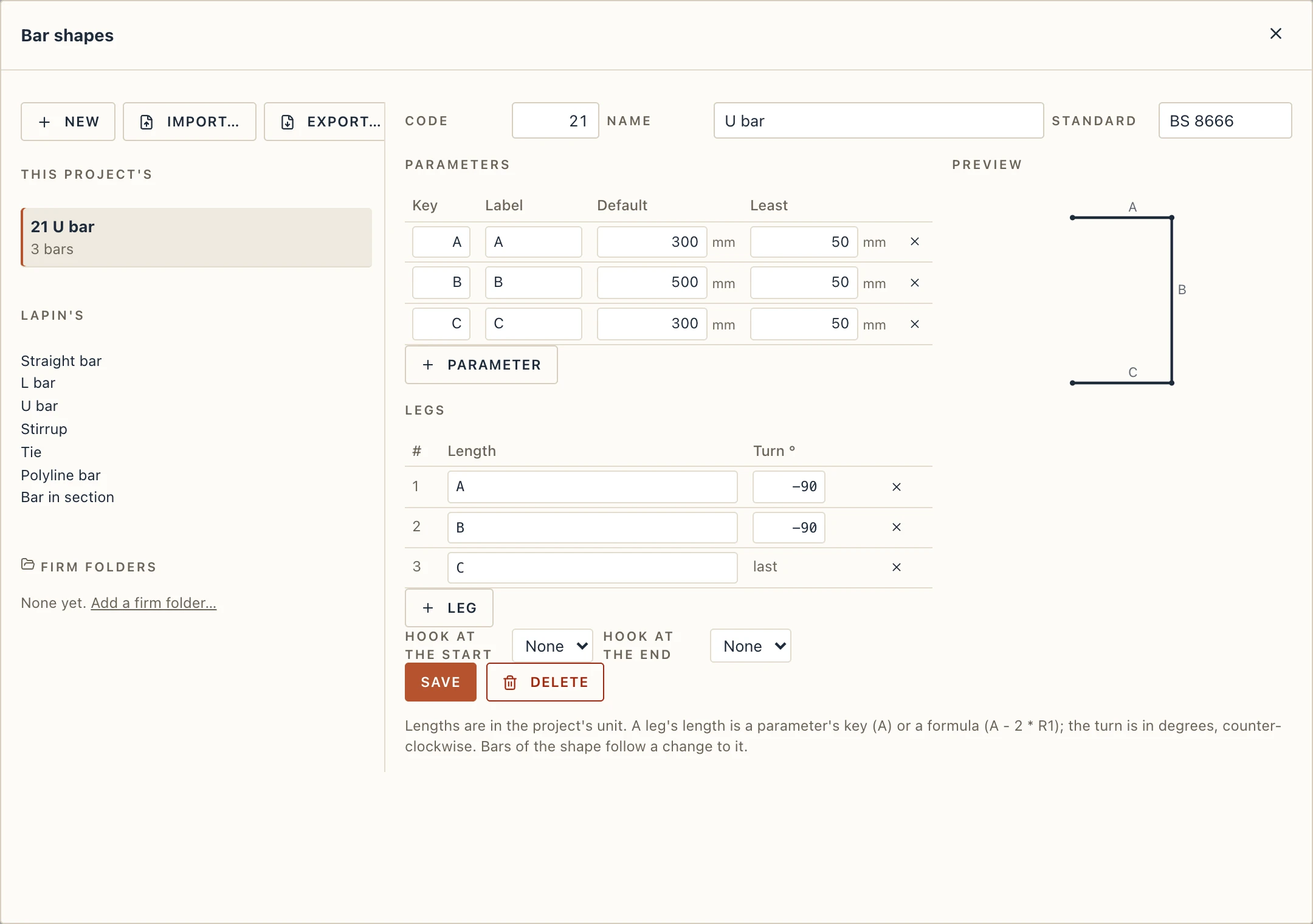
A shape is used with the Bar of a shape tool (under the small tools of the Bars group): choose the shape in the command line's bar and click where the bar goes. Its parameters are then in the bar's properties, in millimetres, like those of the other bars, and its grips drag them. A bar keeps its shape's definition and follows a change you make to the shape. Shapes travel in a .lapinbarshapes file: Export… writes one, and Import… adds the shapes the project lacks and updates those with the same code.

Bars along an element's edges
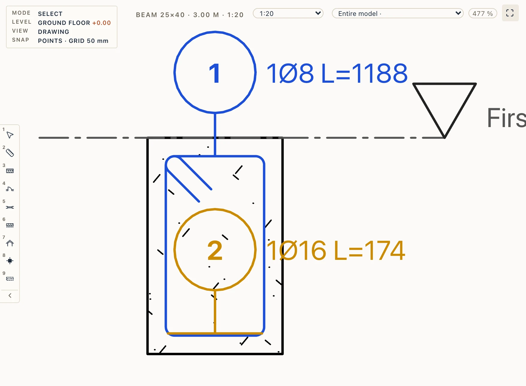
Bars along edges (Simple rebar → Bars, under the small tools) lays a bar along the sides of an element's cut, where a section cuts it: the stirrup of a beam, the bars at its bottom face. Work in a section across the element (Section here and Section across make one). The command line's bar has:
- Cover, in millimetres: how far the bar stands in from the concrete face, to the edge of the bar (the engine brings the outline in by the cover and half the bar's diameter);
- Diameter, from the diameters of the project's rule pack (see Rules below), and Steel;
- All round or Pick edges;
- the Partition new bars go in, as for the other tools.
Click inside the element's cut, in the concrete, not on its edge, and press Enter. With All round the bar is a closed stirrup along the whole outline: a rectangle in a rectangular beam, any outline in any other. With Pick edges the first click only says which cut; each next click, near a side, picks that side or, clicked again, lets it go; Enter then lays an open bar along the sides picked. They have to follow one another round the outline (the bottom side alone, or the bottom and the two beside it). The bar stops at the cover from the faces it meets. It is laid in its host like any bar drawn in its cut, counted in the schedule and drawn as a dot in the other sections. One undo step takes it back.

Stirrups on the beam's or column's type
Stirrups are not drawn one by one: they belong to the type. In Structure → Structure types, a rectangular beam or column type takes Stirrups on this type: their diameter, the concrete cover, and how they are laid — one step throughout, or three zones, each a share of the length (a third by default) at its own step, closer at the ends. Every element of the type then shows them in every section as the view lies to the axis: the rectangle inside the cover in a cross-section, a line for each stirrup in a longitudinal one, lines over the beam in a structural plan; with the label 41Ø8/150 and the mark's balloon. They are counted in the bar schedule under the type's mark. A column's stirrups may be the perimeter's alone, with a diamond inside (its corners at the sides' middles) or with two inside, one each way, each kind a mark of its own. A column is reinforced storey by storey, so its longitudinal bars are on its type too: so many on each face with the corners shared, their diameter, and the starter bars running past the top (1 m by default) for the column above; dots in its horizontal cut and in a structural plan, lines in a vertical section. At the top says how they end: By the column above (the default) runs them on as starter bars where a column stands on this one and, where none does (the top storey), stops them under the top, inside the cover, with a 90° hook (12Ø) bent inwards; Starter bars past the top and 90° hooks inside the top choose one whatever stands above. A hooked bar is an L bar in the schedule, its hook counted in its length.
A beam's longitudinal bars are not on the type (they run over several spans): draw them in the longitudinal section or in the plan, with their hooks. A bar drawn inside a beam's cut belongs to that beam and stands in space: Across the drawing lays it so many times along the view's direction, by the cover (the first and the last at the faces, inside the cover and the stirrup, the rest spread evenly) or at a step. The cross-section then shows the bars as dots where they are, a structural plan as lines, and the schedule counts them all: 3Ø16 L=6400. The same holds for a bar drawn in the cut of a column, a wall, a slab, a footing or a stair. In a stair the bars are laid between the concrete faces of its flights and landings, never its railings or finish.
Bars in 3D (View → Bars in 3D, or the button in this tab) shows or hides the 3D view's Rebar category, the same as its row in Visibility / Graphics (VV): every bar in space as a tube of its diameter swept along its bent shape, in its colour, the type's stirrups at their stations, the column's bars, the bars you drew with their copies. Every 3D view leaves the bars out until you show them, whatever its style; a hidden beam takes its stirrups with it. A linked or imported structural IFC's bars (IfcReinforcingBar) are in the same category: they show and hide with these, shared where they repeat so thousands turn smoothly, and plans and sections draw them only at LOD 400 (a structural style's). The bars of this tab are a picture for the screen, asked of the engine while they show: they are not picked, not exported, and past two million triangles only the first are drawn. Bars of their own in the model, generated from the types, with optimisers and configurators, are for the premium Rebar BIM.
Stirrups along a beam
Stirrups along takes the two ends of a path; the stirrups are spread so one stands at each end, at the step you set (150 mm by default). Zones change the step along the way: Thirds puts a step half as close at each end, as a seismic beam asks; the label says 25Ø8/100-200. Show all of them, only the ends and the middle with a dashed line between, or one.
The schedule
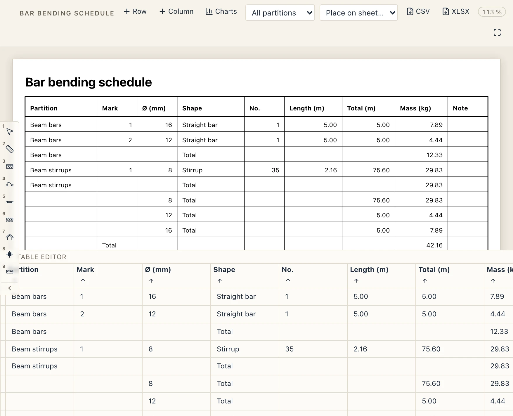
Bar schedule makes a schedule of every bar by mark: diameter, shape, number, length of one, total length and mass, with the totals by diameter. A mark whose bars differ in diameter or length is noted. It is a schedule like the others: on sheets, in CSV and XLSX.
The bending schedule by the standard
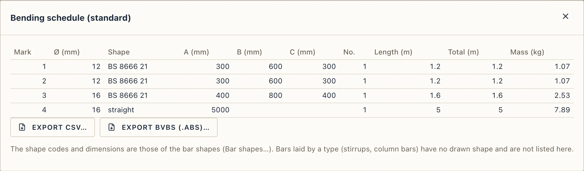
Bar schedule (above) is the project's schedule of bars. Bending schedule (standard) writes the marks the way your standard's bar list does, one row for each mark: mark, diameter, shape code, the dimensions A, B, C… of the shape's parameters, the number, the length, the total and the mass. It lists the bars drawn from a shape (those of the Bars group and of your own shapes). The bars laid by a type (stirrups, column bars) have no drawn shape and are not in it.
Export CSV… writes the table for a spreadsheet (UTF-8, with the byte order mark so a spreadsheet opens it right). Export BVBS (.abs)…, here and in the tab's schedule group, writes the marks for the bending machine in BVBS, the German association's format (BF2D records, after the public guideline 3.1, with its checksum). The notice says how many records it made, and how many bars laid by types were left out.
Rules, and bars from drawn lines
The steels and diameters the tools offer, the default steel, and the mandrel and the hook tails new bars take come from the project's rule pack (Manage → Rules…; see Rules): change a diameter there and every picker follows. Nothing is refused for a rule: Lapin proposes and warns.
Lines, polylines and circles drawn in a view, or imported from a DXF, can be made bars with Convert drafting to… (see Drafting): a straight line becomes a straight bar, a polyline a bar of the shape it has (an L, a U or a stirrup is recognised, else a polyline bar), laid in the view like any bar. Convert layers… does it for a whole drawing, choosing what each layer becomes.
Partitions
A partition sorts bars into sets of their own, as in Revit: beam stirrups, beam longitudinal bars, wall bars, a storey. It is a text on each bar or distribution (Partition in Properties).
- Drawing in one: the drawing tools' bar has a Partition box. New bars go into the partition typed there, and it lists the ones the model already has.
- Marks: each partition numbers its bars from 1, so mark 1 can be in several.
- On types: stirrups and column bars set on a type have a partition each, in the Structure types dialog.
- The schedule: with partitions it gains a Partition column, lists each one's marks apart and adds its mass after them. Its toolbar shows all partitions or one.
- Views: a view filter with a parameter rule on Partition (Manage → View filters) hides or colours a partition's bars, like any other filter.
Rebar settings holds the project's choices: a colour for each diameter, the text and balloon sizes on paper, the steel, the cover, the segment lengths written along the bars, and the labels' style for each kind.