User guide
Steel
Steel members with configurable ends — extended or set back, cut by a plane, mitred, fitted to another member, coped — made from a drafted outline too; hollow and cold-formed sections; portal frame halls with haunches, their connections and their secondary steel.
The Steel tab

- Portal frame hall…: a whole steel hall from a few numbers, in the hall configurator (below).
- Column: a column of the structure, placed with one click on the storey, of a steel profile: an HEB 200 by default, from the built-in EN catalogue (its column type is made the first time and used again). Change its profile in Properties or in Structure → Structure types; the Structure tab's own Column tool places the project's current column type as before.
- Member (SM): a steel member along two points, on the storey's top with its section's top on the axis, as a beam. Its type is chosen in Properties before the first click, or from the Catalog tab, where each steel type is drawn by its section.
- Convert to member: the selected drafted outlines made members (below).
- Mitre and Fit: two members joined at their ends (below).
- Steel types: the project's member types, and new ones.
- Find connections, Anchor plan, Frame elevation, Steel members and Steel parts: connections, drawings and lists (below).
A member is an IfcMember: its axis runs anywhere in space (a brace, a rafter, a post), its section comes from its type, it can be turned about its axis (Rotation) and its axis can run through the section's centre, top or bottom (Insertion point). The structure's beams and columns of a steel profile take the same ends.
Ends
Select a member, or a straight beam or column of a steel profile: its Steel section in Properties shows its two ends, Start and End. Each end is a set of rules; the body follows them.
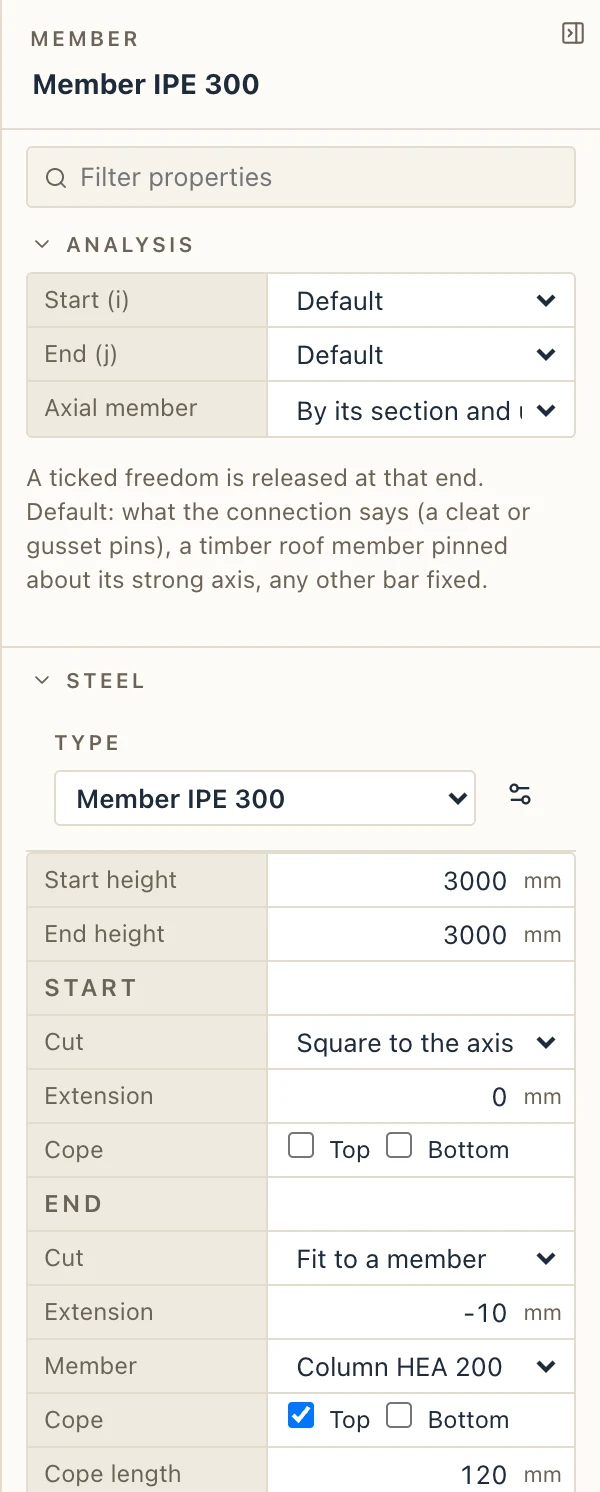
- Extension: how far the end reaches past its point; negative, it is set back (a fitting gap).
- Cut: Square to the axis; By a plane, turned from square In plan (about the section's up) and In elevation (about its side), in degrees; Mitre with another member, on the plane halving the corner between them; Fit to a member, on the face of the other member it comes to (a column's flange, or its web's side when the column is turned).
- Cope: the flanges notched at the Top and/or the Bottom, its Cope length back from the end and its Cope depth from the section's edge, as for a beam framing into a girder.
A mitre and a fit name the other member: move it, and the end follows; delete it, and the end is square again and says so. Mitre on the tab mitres the two members selected at the corner where they meet; Fit fits the first selected to the second.
From a sketch to a member
Draw the member's outline as a closed polyline or a rectangle (Draft), then Steel → Convert to member with one or more outlines selected. It opens Draft → Convert to… on Steel members from outlines (Converting drafting to elements), which shows what each outline makes, or why it is not a band, before you press Convert; there you can also pick a member type to try first, or keep the drafting. In one step each outline is read and replaced by a member:
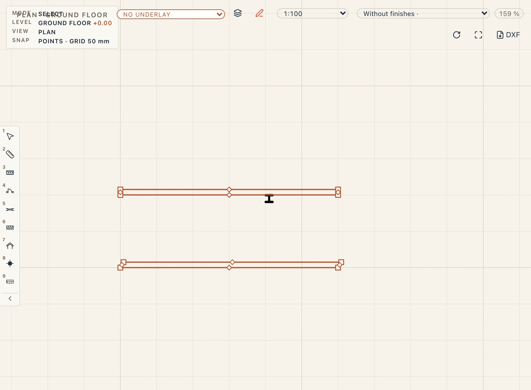
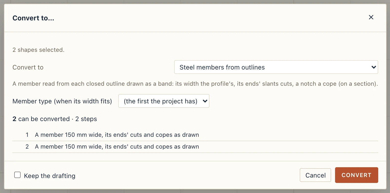
- its two long parallel edges (within half a degree) give the axis, their midline from end to end, and the width between them;
- the edge across each end gives that end's cut: square, or a plane at the edge's slant.
On a plan the outline is the member seen from above: its width is the flanges', and a profile of that width is found among the project's member types and the catalogue (else the type chosen for Member); the member lies on the storey's top. On a section or an elevation the outline is the member seen from the side: its width is the section's depth, a slanted end is a cut in elevation, and a square notch at an end is a cope at the top or the bottom; the member lies where it is drawn. A notch drawn on a plan is refused (a cope is seen from the side). An outline that is not a band (a triangle, an L, edges that are not parallel) is left as it is, and Lapin says so.
Steel types
Steel → Steel types lists the project's member types with their weight per metre, and makes new ones: a profile from the catalogue (IPE, HEA, HEB, UPN, L, RHS, CHS and the generic cold-formed C, Z and Σ) or a hollow or cold-formed section of its own dimensions (depth, width, thickness, lips). The new type can be a member type, or a beam type or column type of the structure, so the Beam and Column tools place steel too. A click on a type in the list makes it the one Member places.
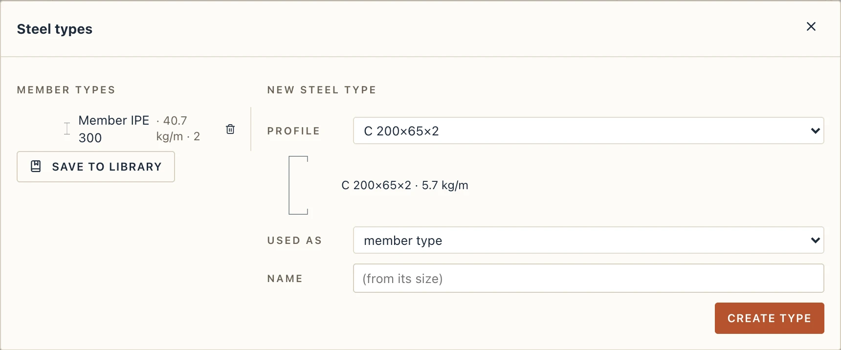
Any other profile comes from the libraries: From a profile library… searches them all (see Profile libraries).
Hollow sections are open inside, in the 3D view, the sections and the quantities. The cold-formed sections are generic shapes with dimensions, their bends sharp, without a manufacturer's catalogue.
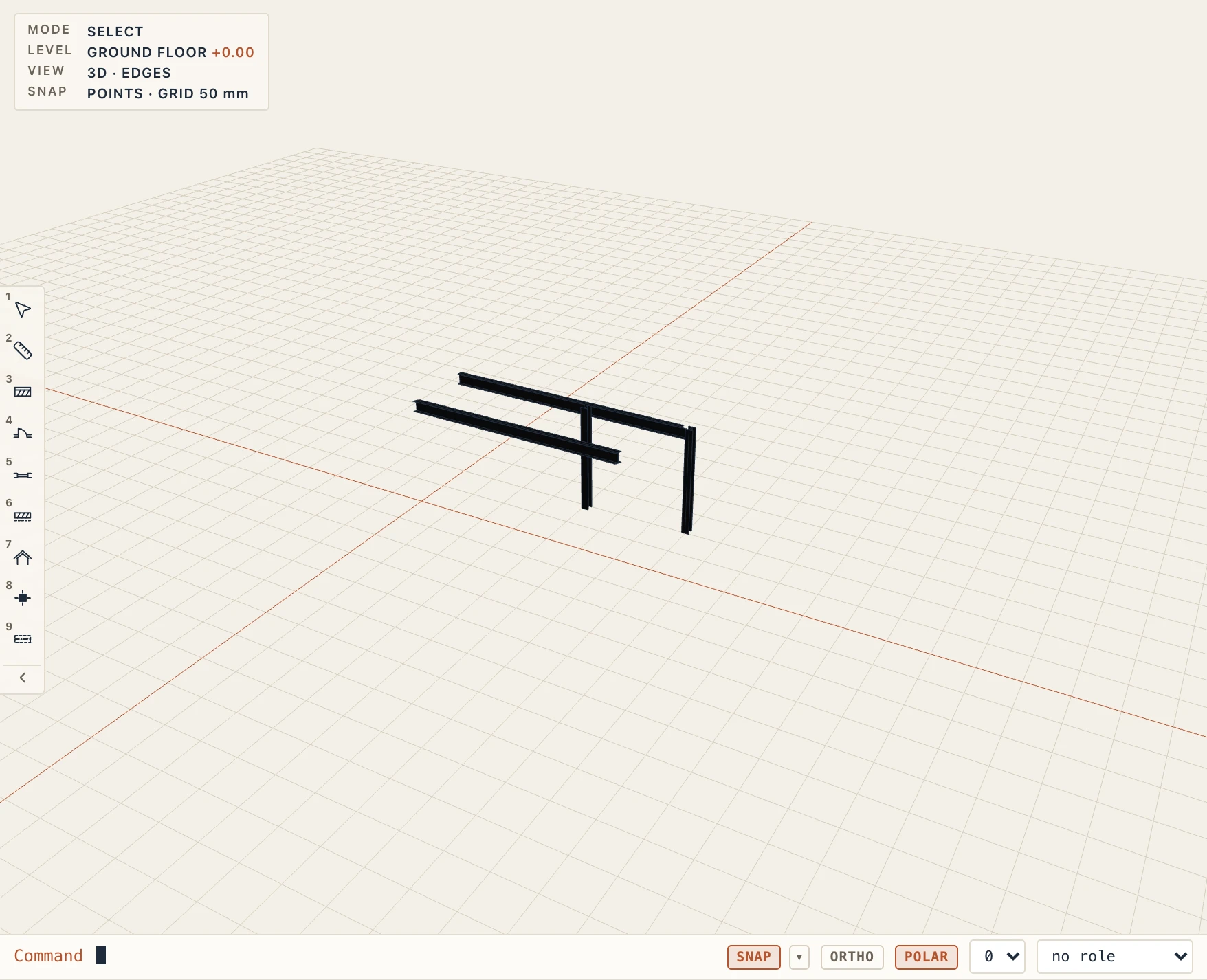
Portal frame halls
Steel → Portal frame hall… opens the hall configurator. Like the roof's, it has the styles on the left, the hall's fields in tabs in the middle and, on the right, the hall as Lapin would build it: a typical frame seen along the hall, with its haunches, and a summary of what it weighs.
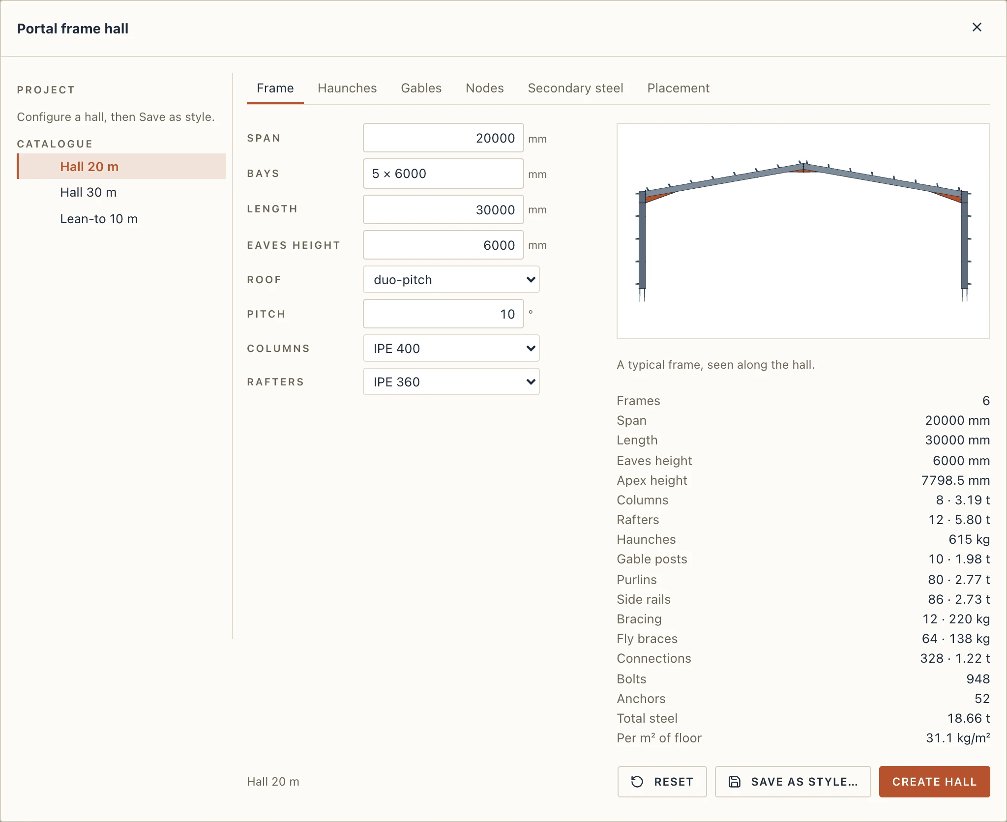
- Styles: the catalogue's typical halls (Hall 20 m, Hall 30 m, a mono-pitch Lean-to 10 m) and the project's own. A style picked fills every field in; any field may then be changed. Save as style… keeps the hall as it is configured as a style of the project; Update style saves it again into its style, and every hall of that style follows.
- Frame: the Span (column axis to column axis), the Bays, from frame to frame, in the project's unit (equal ones as
5 × 6000, or each listed:6000, 6000, 7500; a length may carry its own unit,6m, and a bare number under a metre is read as metres, so5 × 6still means five 6 m bays), the hall's Length (typed, it keeps the number of bays and makes them equal), the Eaves height (the rafters' top over the column's outer face), the Roof (duo-pitch or mono-pitch) and its Pitch, the Columns' and Rafters' profiles. - Haunches: the Haunch at the eaves and the Haunch at the apex, each with its Length along the rafter from the column's face (or the apex) and its Depth below the rafter there, and how it is Made: cut from the rafter's section (an I cut obliquely along its web, one half welded under the rafter: the rafter's own web and flange) or welded from plates (a Web plate and a Flange plate of their own thickness, and the flange's width).
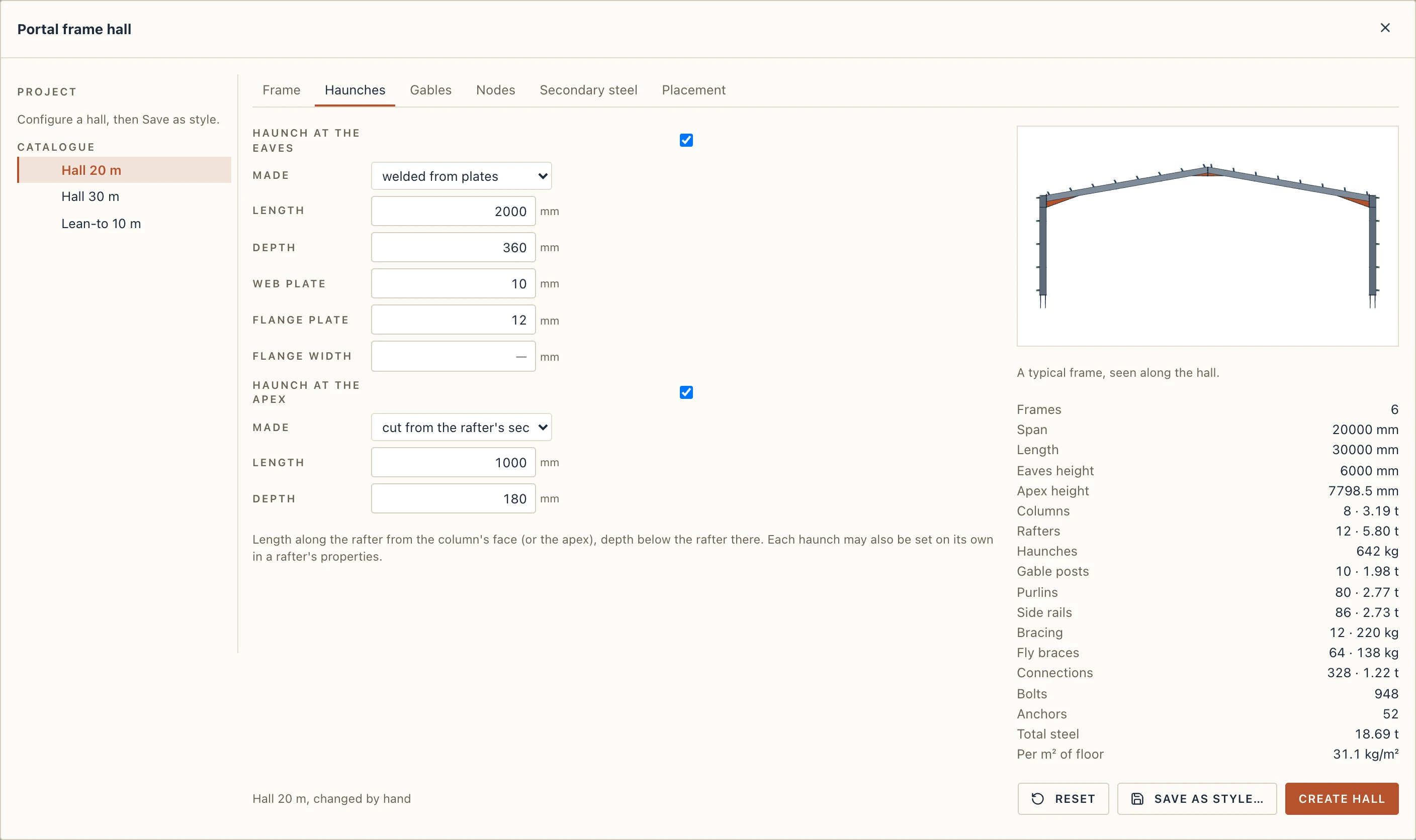
- Gables: gable posts under a simple rafter (corner posts and posts at the Post spacing, their strong axis across the gable wall, under a lighter rafter that runs to the walls' outer line, the posts fitted to its underside), or a regular frame at each end.
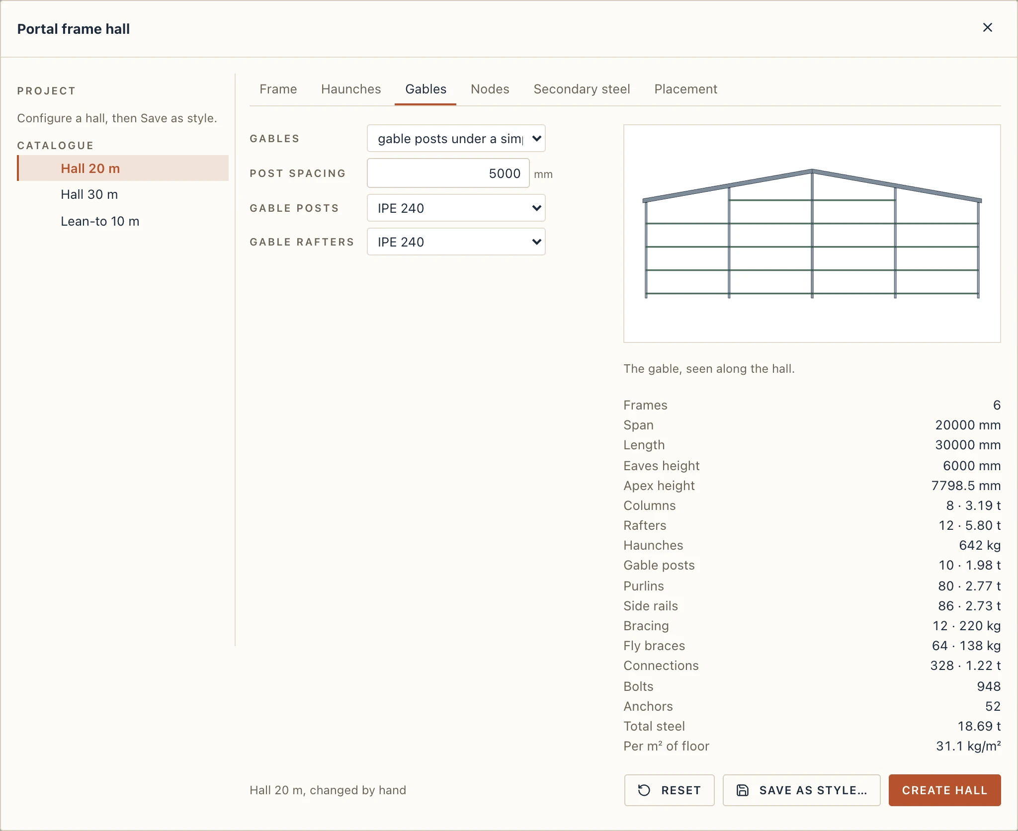
- Secondary steel: the purlins, side rails, bracing, eaves beam and fly braces (below).
- Placement: where axis A and axis 1 cross, and the span's direction in plan (Rotation); the preview shows the hall's grid from above.
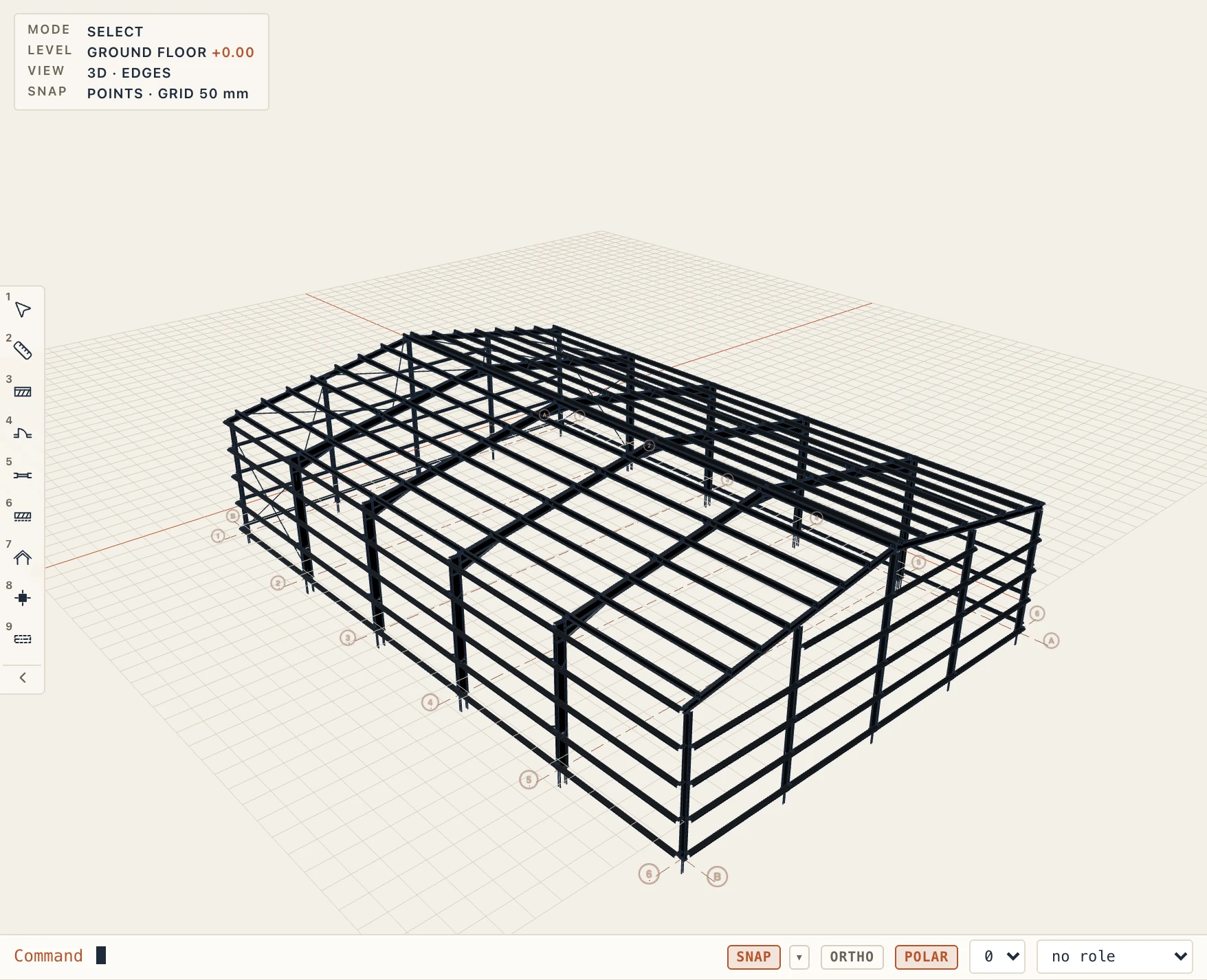
Create hall makes it in one step, which one undo takes back: its own grid (axes 1, 2… at the frames, A and B at the columns), and at each frame two columns (the structure's columns of a steel profile, their web in the frame's plane, their top cut along the roof's slope) and two rafters mitred at the apex (one, from the low column to the high one, on a mono-pitch roof): steel members fitted to the columns' faces, with their haunches. The hall stands on the current storey; the eaves and the apex are heights of its frames, not new storeys. The summary gives the frames, the heights, and the steel by kind: columns, rafters, haunches, gable posts, in all and per m² of floor.
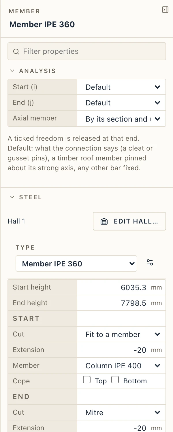
The hall stays editable. Select one of its members: its Steel section shows its hall and Edit hall…, which opens the configurator on it; Apply builds the hall again over the same members, which keep their identity (a member no longer needed goes, a new one is added). A rafter's haunches are also listed there, each changed on its own (its kind, length, depth, plates): a haunch set so stays as it is when the hall is built again; × takes it off.
Connections
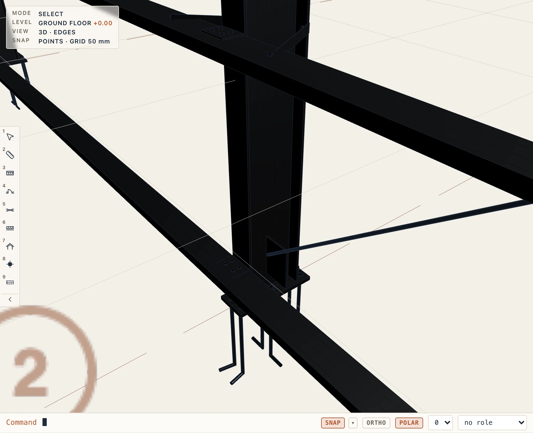
A hall's frames come with their connections (Steel → Portal frame hall…, tab Nodes): a column base under every column and gable post, an eaves connection where each rafter comes to its column, an apex connection where two rafters meet, and a fin plate under the rafter over each gable post. Each one is an element of its own that knows the members it joins; its plates, bolts and anchors are made from its parameters and from the members as they are, so they follow when the hall is changed.
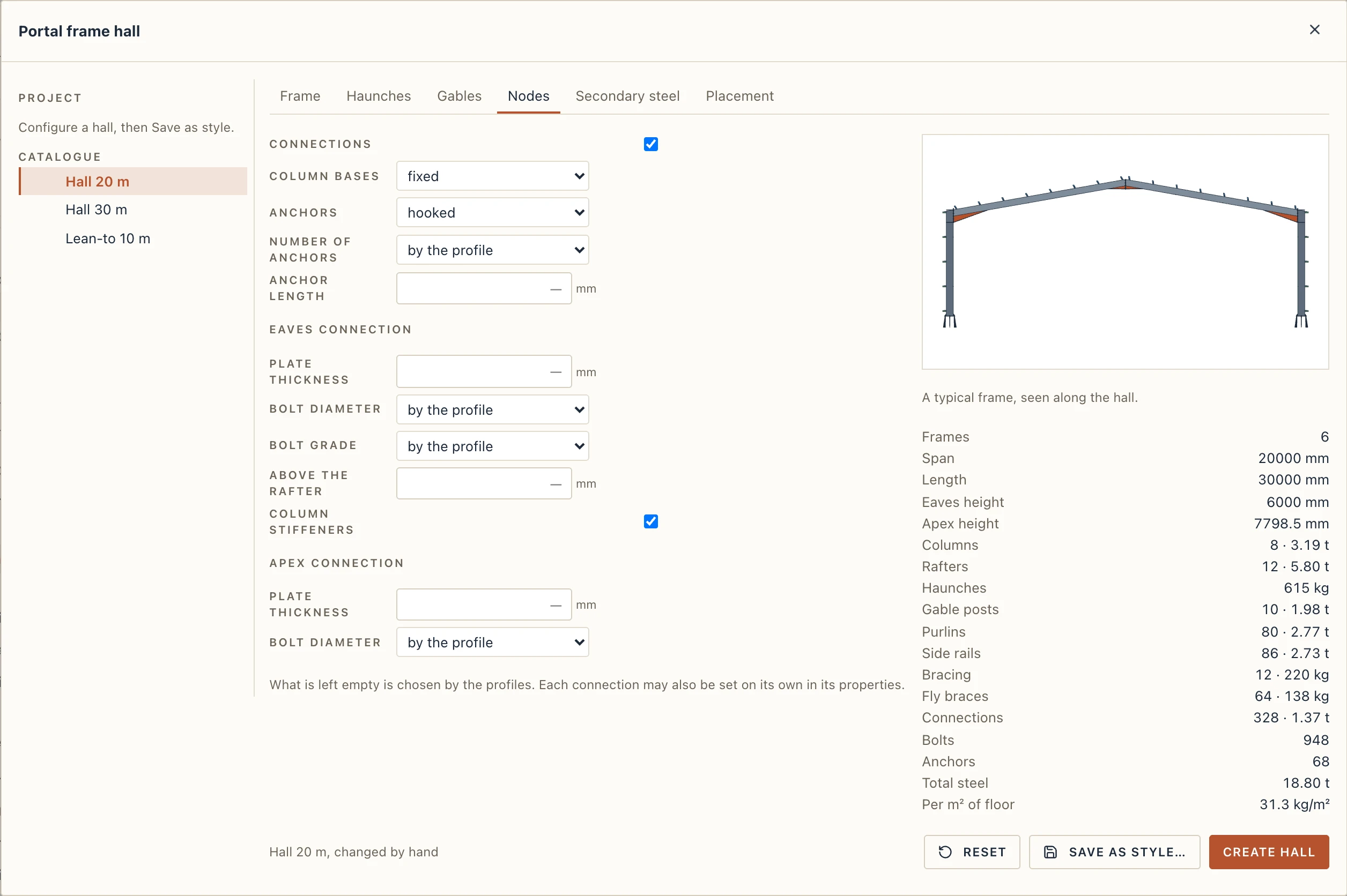
- Connections: on or off for the whole hall.
- Column bases: pinned (a base plate, two anchors either side of the web or four inside the flanges) or fixed (a longer, thicker plate, four to eight anchors outside the flanges, ribs in the web's plane). The Anchors are straight, hooked or with an anchor plate at their foot; the Number of anchors and the Anchor length (below the concrete's top) are chosen by the profile when left empty. When a footing of the structure stands under the column, the anchors go into it (and stop 50 mm above its bottom); otherwise they go their length under the grout.
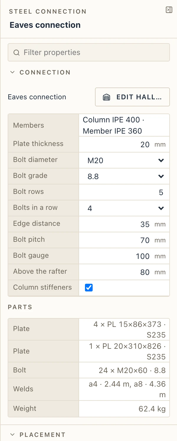
- Eaves connection: an extended end plate on the rafter bolted to the column's flange: its Plate thickness, the Bolt diameter and Bolt grade, how far it stands Above the rafter (a row of bolts there), and the Column stiffeners in line with the rafter's top flange and its haunch's flange.
- Apex connection: the two rafters' end plates bolted together on the mitre, with their haunches.
What is left empty is chosen by the profiles: M16 to M27 bolts by the depth of the member bolted, a plate as thick as its bolts, edges and pitches from the holes. A connection sets back the ends of its members by what it puts between them (a rafter by its end plate, a column by its base plate, a gable post by a 20 mm gap), through the members' own end rules.
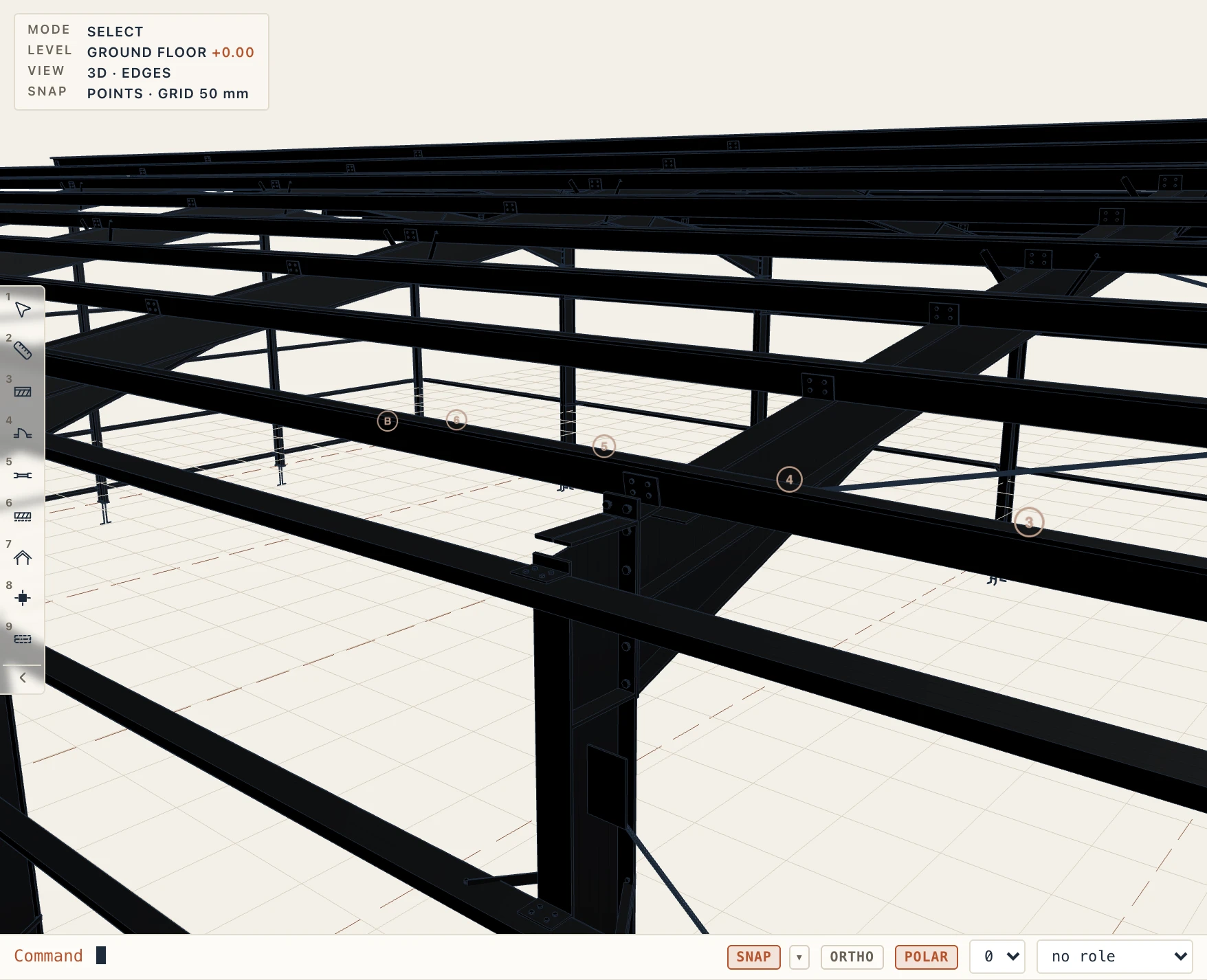
Select a connection to see it in Properties: the members it joins, every parameter as it is now (a size chosen by the profile is shown as such), and its parts: plates, bolts and anchors by size and grade, the welds by throat with their length, its weight, the footing its anchors go into. A parameter changed there is set on that connection alone, and a hall built again keeps it. Edit hall… opens its hall.
Members drawn by hand get their connections from Steel → Find connections: a base under each vertical member, an eaves where a member is fitted to a column, a gable post's where a post is fitted under a member, an apex where two members are mitred with each other, a splice where two run in line end to end; for the selected members, or the whole model when nothing is selected. Steel → Steel parts makes the schedule of the connections' plates, bolts, anchors and welds. Deleting a connection gives its members their ends back; deleting a member takes its connections with it; Delete hall in the configurator takes the hall away with its members, connections and grid, in one step.
Secondary steel
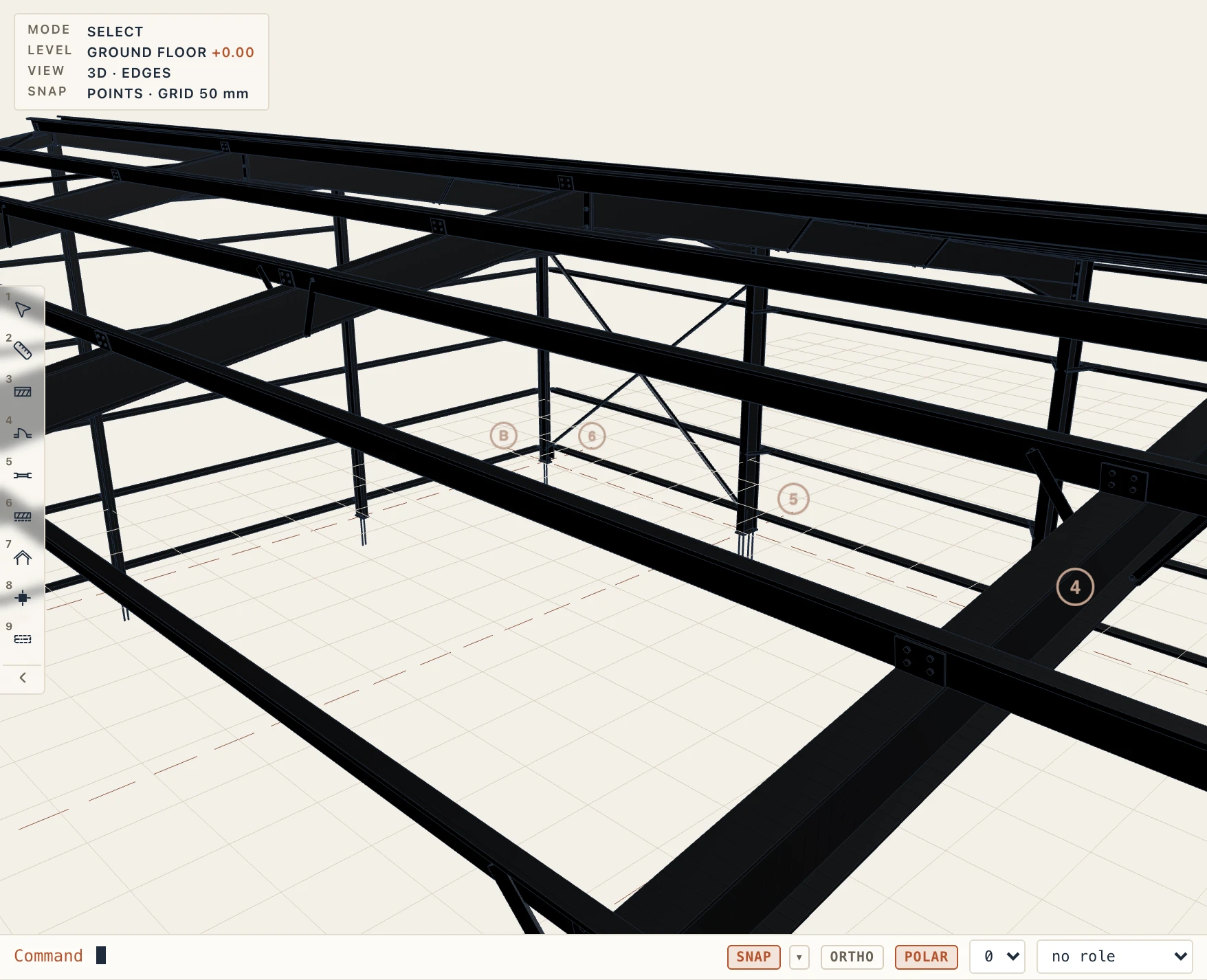
A hall comes with its secondary steel (Steel → Portal frame hall…, tab Secondary steel), built with it and again with it when it is changed, each member keeping its identity:
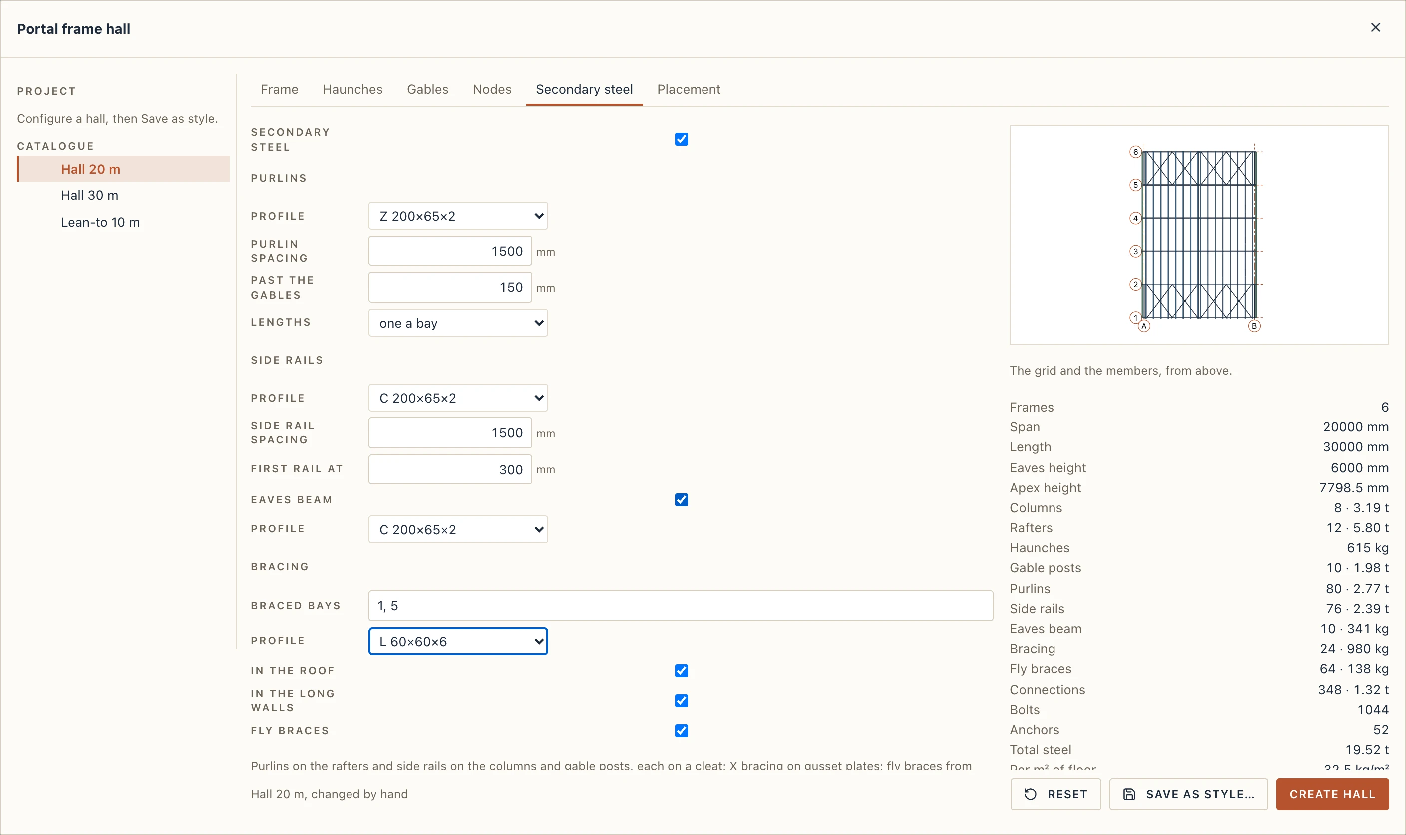
- Secondary steel: on or off for the whole hall.
- Purlins: their Profile (the cold-formed Z, C and Σ, a channel or a light I), the Purlin spacing along the slope, how far they run Past the gables, and their Lengths: one a bay (frame to frame) or continuous (the hall's length). They stand on the rafters' top, their web square to the roof, from 150 mm inside the columns' face to 200 mm short of the apex, in as many lines as the spacing asks.
- Side rails: their Profile and the Side rail spacing, from the First rail at up to under the eaves, one a bay on the columns' outer face, their web level and their toes down; on the gables, from post to post (or column to column of a gable frame), as high as the rafter over them lets. An Eaves beam takes the top of the long walls (its own Profile), the rails a spacing under it.
- Bracing: the Braced bays (their numbers, from the first), the bars' Profile (round bars from Ø16 to Ø30, angles or tubes), and where: In the roof (an X in the roof's plane, under the rafters' top flange, in panels about as long as the bay) and In the long walls (an X in the walls' plane through the columns' axes, from the first rail's height to under the haunch).
- Fly braces: from every second purlin and side rail down to the rafter's bottom flange and the column's inner flange, either side, clear of the haunches.
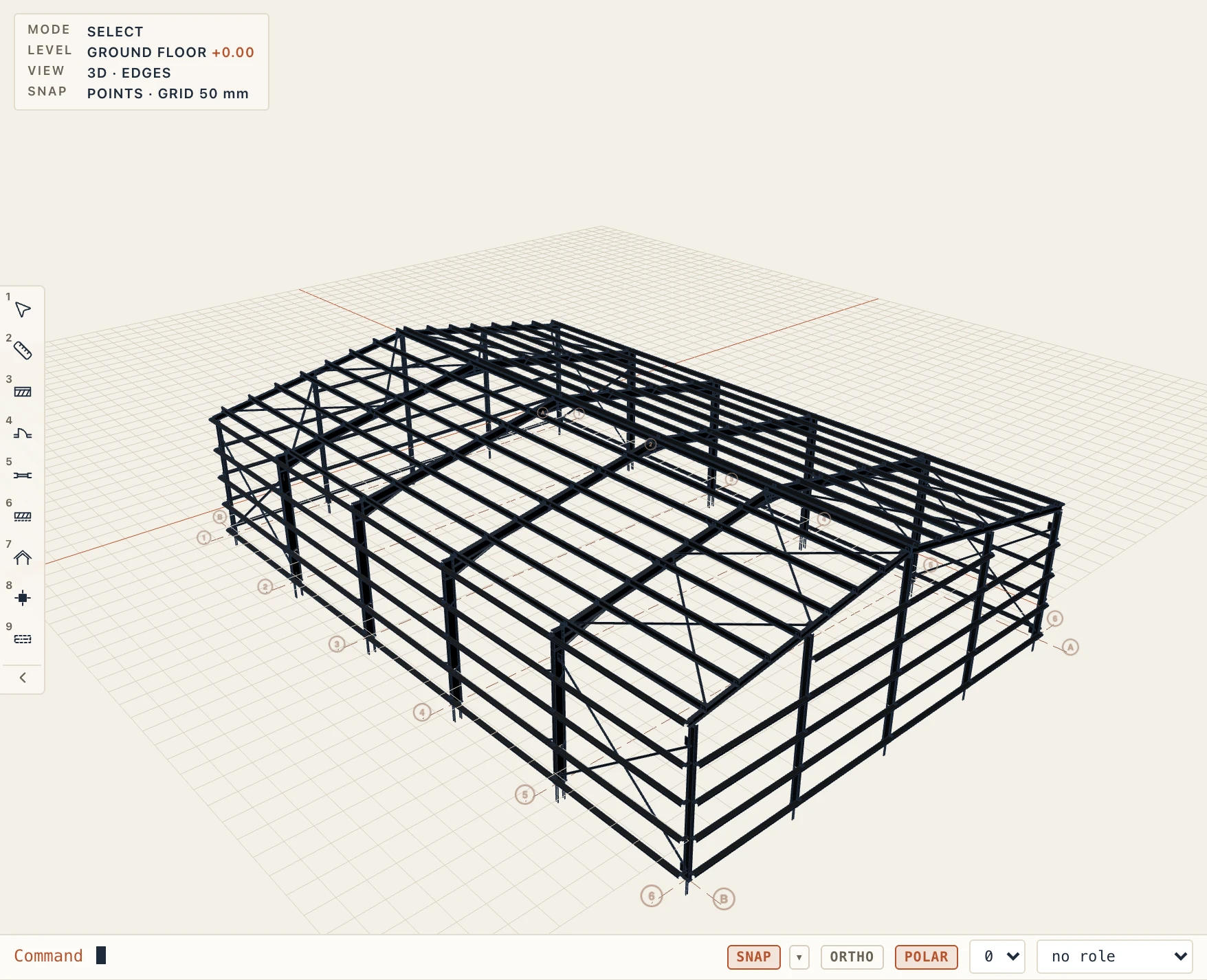
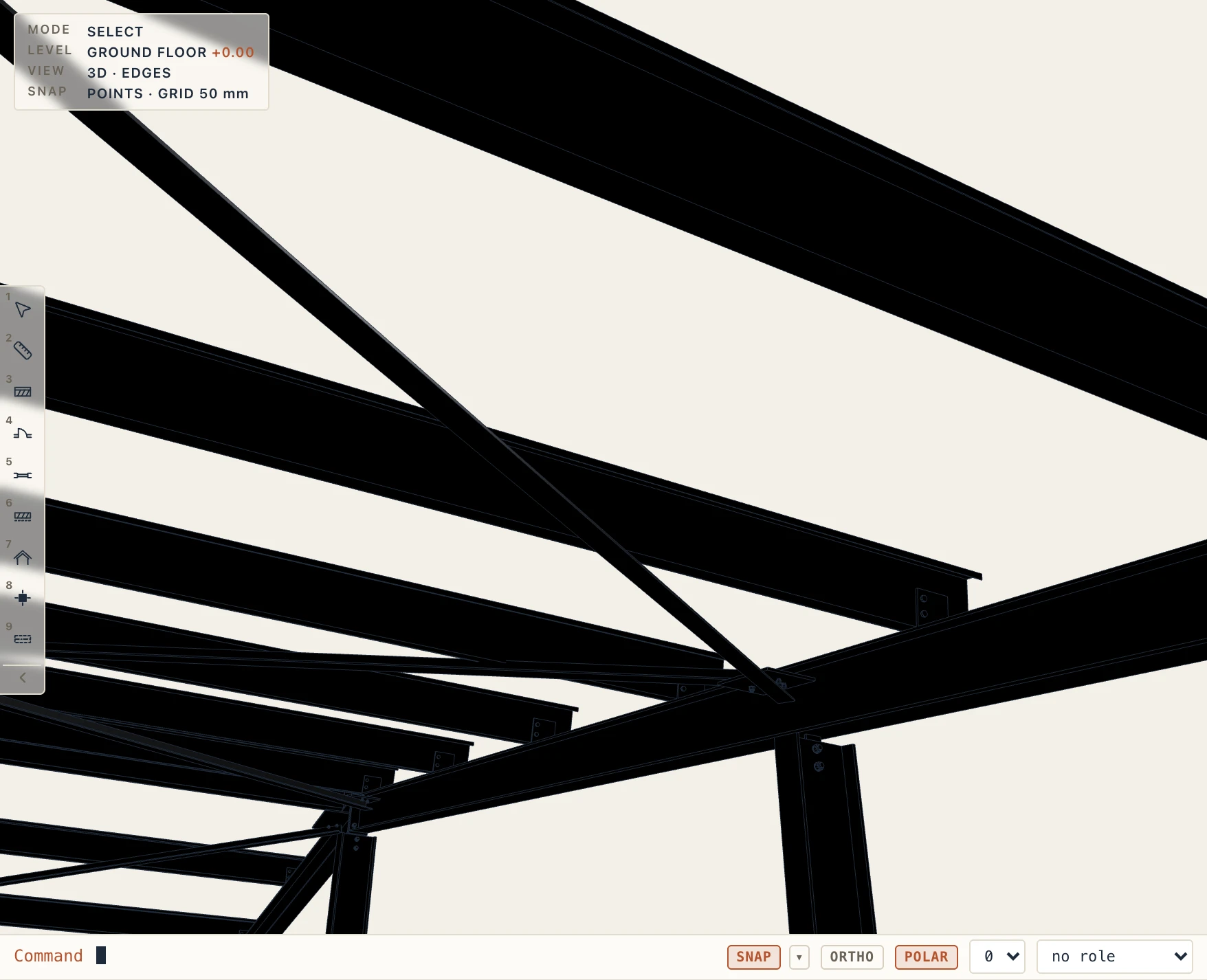
Each purlin and rail sits on a cleat on every rafter, column or post it crosses: a plate welded to the member's face, beside the purlin's web (outside a C's, on the side of a Z away from its bottom flange), bolted through the web, two bolts a purlin end (M12 on a purlin up to 250 mm deep, M16 over). A corner post narrower than the columns gets a taller cleat, up to the rail. Each X sits on gusset plates welded to the rafters' or the columns' web, a diagonal on each face; an angle or a tube is bolted to it with two bolts, a round bar's threaded end takes its nut. A fly brace is bolted at both ends. They are connections like the frames': select one to see its plate and bolts in Properties, and change them there. The configurator's summary counts and weighs the purlins, rails, eaves beam, bracing and fly braces; the Steel parts schedule has their cleats, gussets and bolts.
Lists and drawings
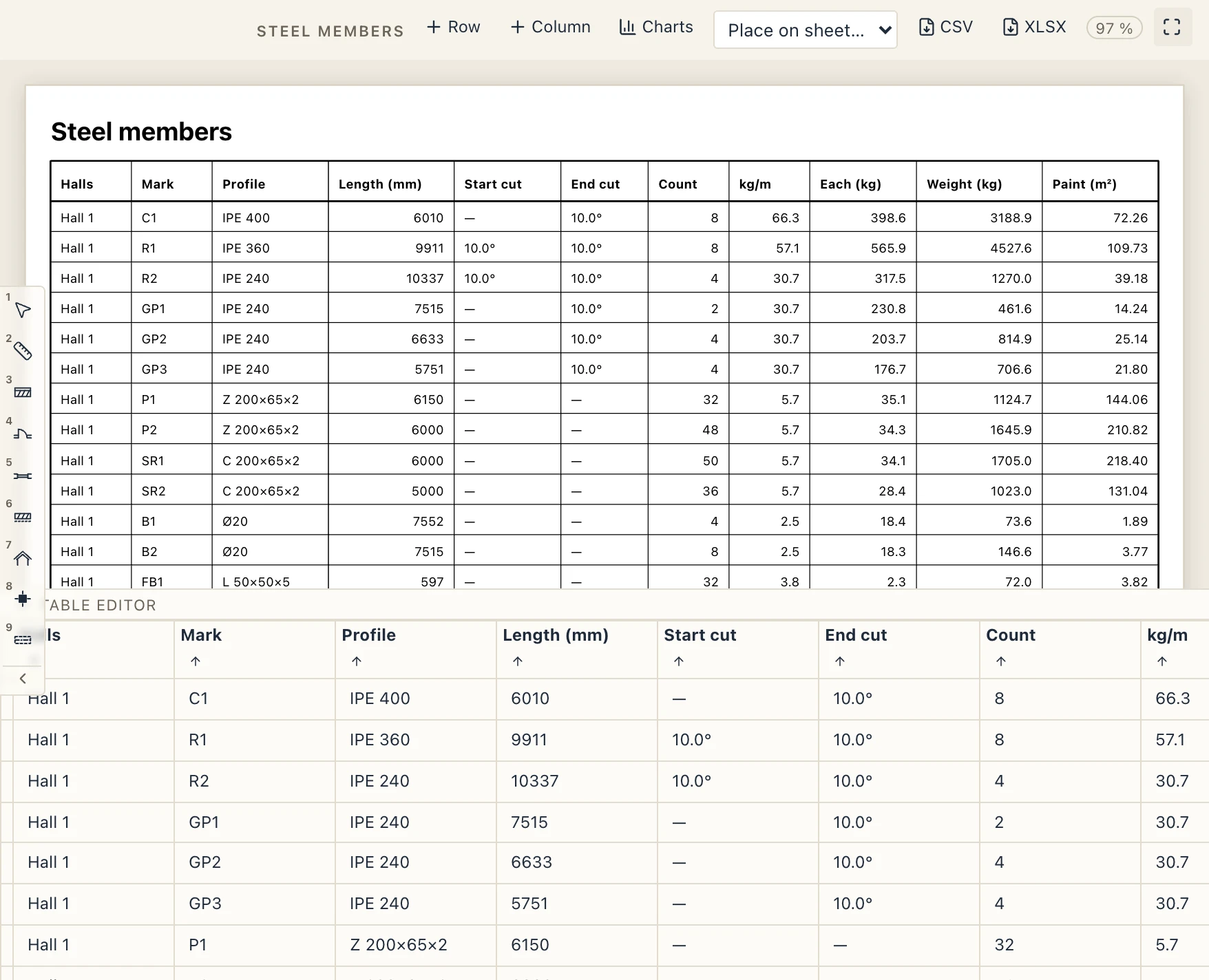
Steel → Steel members makes the list of the project's steel: the members, and the beams and columns of a steel profile, by hall (those of no hall last), each Mark for the members of one kind alike in profile, length and end cuts (C columns, R rafters, GP gable posts, P purlins, SR side rails, EB eaves beams, B bracing, FB fly braces, M other members, BM beams), numbered from the heaviest profile and the longest. A row gives the Profile, the Length, the Start cut and End cut (how far the end's plane turns from square, and a cope: the cutting list's angles), the Count, the weight per metre, Each and in all, and the area to Paint; a total under each hall, and one for all. Steel parts lists the connections' plates, bolts, anchors and welds, the cleats and gussets with them.
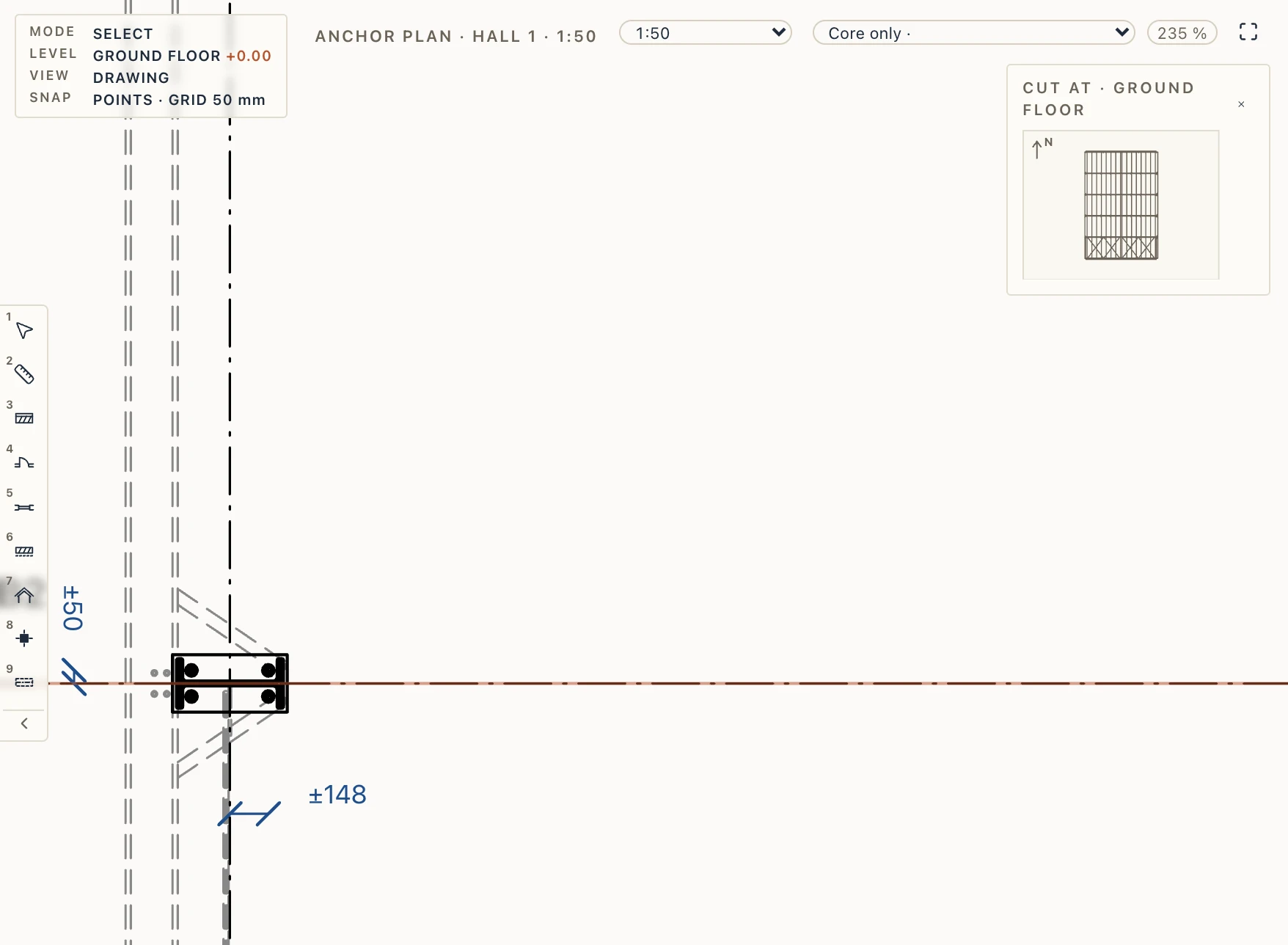
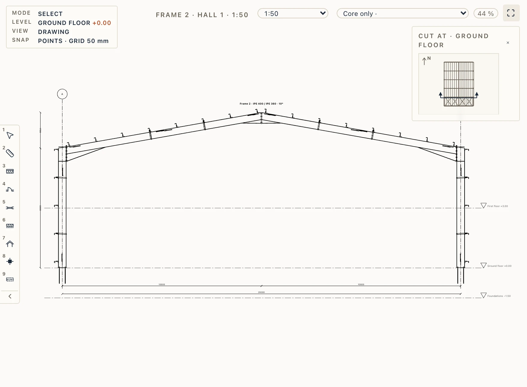
Steel → Anchor plan draws the hall's column bases for the foundations: a plan of the hall's storey at 1:50, cut just over the base plates, with each anchor circled, its distance to the grid axis (± when the anchors stand symmetrically about it), each base marked by its type (B1, B2…: the same plate, anchors, grade and grout), the grid's bays and span, and the table of the types beside the hall: their count, kind, plate, anchors (number, size, shape), grade and grout. Steel → Frame elevation draws a frame (the typical one, or the frame of the member selected) seen along the hall at 1:50, with its span, its eaves and apex heights. Both are views of the hall (asked again, the same view opens) and go on sheets like any other; they follow the hall when it is changed.
IFC and quantities
A member exports as an IfcMember with its IfcMemberType. Its body is written as the other programs write steel (Tekla, Advance Steel, Revit): its section extruded (IfcExtrudedAreaSolid), clipped by its ends' planes (IfcBooleanClippingResult with IfcHalfSpaceSolid), and each cope an IfcOpeningElement voiding it. A steel beam or column with ends is written the same way. Each member's quantities give its length between its cuts, its section's area, its volume and its net weight (7850 kg/m³).
A hall exports as an IfcBuildingSystem (LOADBEARING) its members and connections are assigned to: its purlins IfcMember PURLIN, its bracing and fly braces BRACE, its side rails and eaves beam USERDEFINED (Side rail, Eaves beam); its spec as the property set Lapin_SteelHall, with its own IfcGrid. A rafter with haunches is an IfcElementAssembly of the rafter and its haunches: a haunch cut from the section is an IfcMember, one welded from plates two IfcPlates, each swept (IfcExtrudedAreaSolid). The haunches are left out of the rafter's own quantities; the configurator's summary weighs them.
A connection exports as an IfcElementAssembly of its plates (IfcPlate), bolts (IfcMechanicalFastener BOLT), anchors (ANCHORBOLT) and anchor plates (IfcDiscreteAccessory ANCHORPLATE), each with its size and grade in Lapin_SteelPart; it realizes the connection of the members it joins (IfcRelConnectsWithRealizingElements; a base, between the footing and its column). The welds are kept as data, not as bodies.
The bolt grades a connection can take are the Bolts rules of the project: see Rules.