User guide
Floors and roofs
Draw floors and roofs by their outline, choose a roof's shape and edges, and cut openings.
Floors
Choose Architecture → Floor (SB), then click the corners of its outline. Close the outline on the first point, or press Enter. A floor is made of layers too, set in Architecture → Floor types. A layer of a floor type may have a thickness of 0 (a waterproofing, paint): it builds nothing, is drawn as a line in sections and is measured by the floor's area.
In Floor types, the layers run from the top down. The arrows at the end of a layer's row move it up or down one place (they are buttons, reachable with Tab), and Reverse layers runs the whole build-up the other way, so the top layer goes to the underside; it asks first, because every floor of the type turns over once the type is saved.
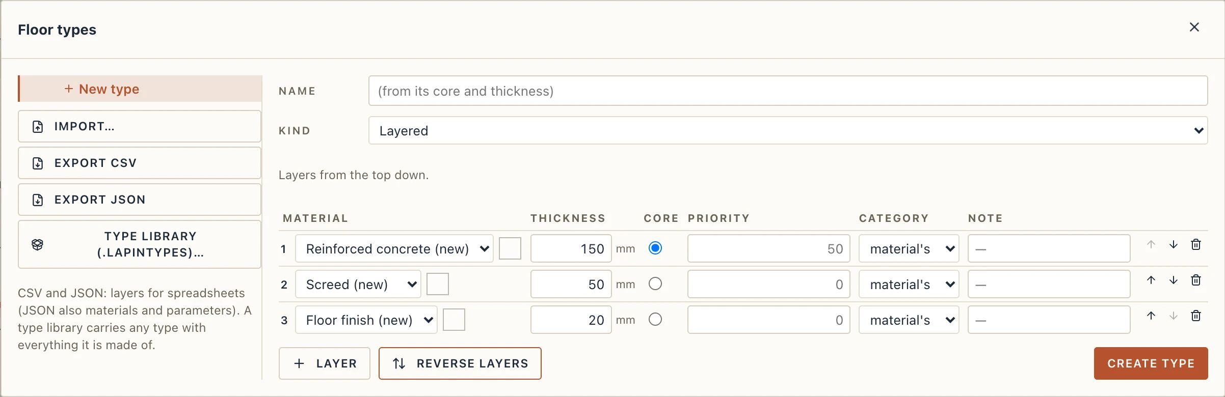
In Floor types, each layer has a Priority (0 to 100) and a Category, as a wall type's layers do. A wall layer that goes down into the floor (Into floors in Wall types) passes the floor's layers of a lower priority and stops on the first as high or higher. Empty, the priority is the material's in Manage → Cut order, else 50 for the core and 0 for the other layers. A layer marked Finish goes when a view leaves out the floors' finishes.
To change the outline, select the floor and drag its corners. To add a corner, hold Ctrl/⌘ and click the small diamond in the middle of an edge, or right-click the selected floor near an edge and choose Add corner here: the new corner goes where you clicked. To remove one, Ctrl/⌘-click it, or right-click it and choose Remove corner (an outline keeps three corners at least). Each is one undo step, and the same works on floor openings, roofs, rooms and balconies. Floor opening (SH) cuts a hole in a floor, for a stair or a shaft.
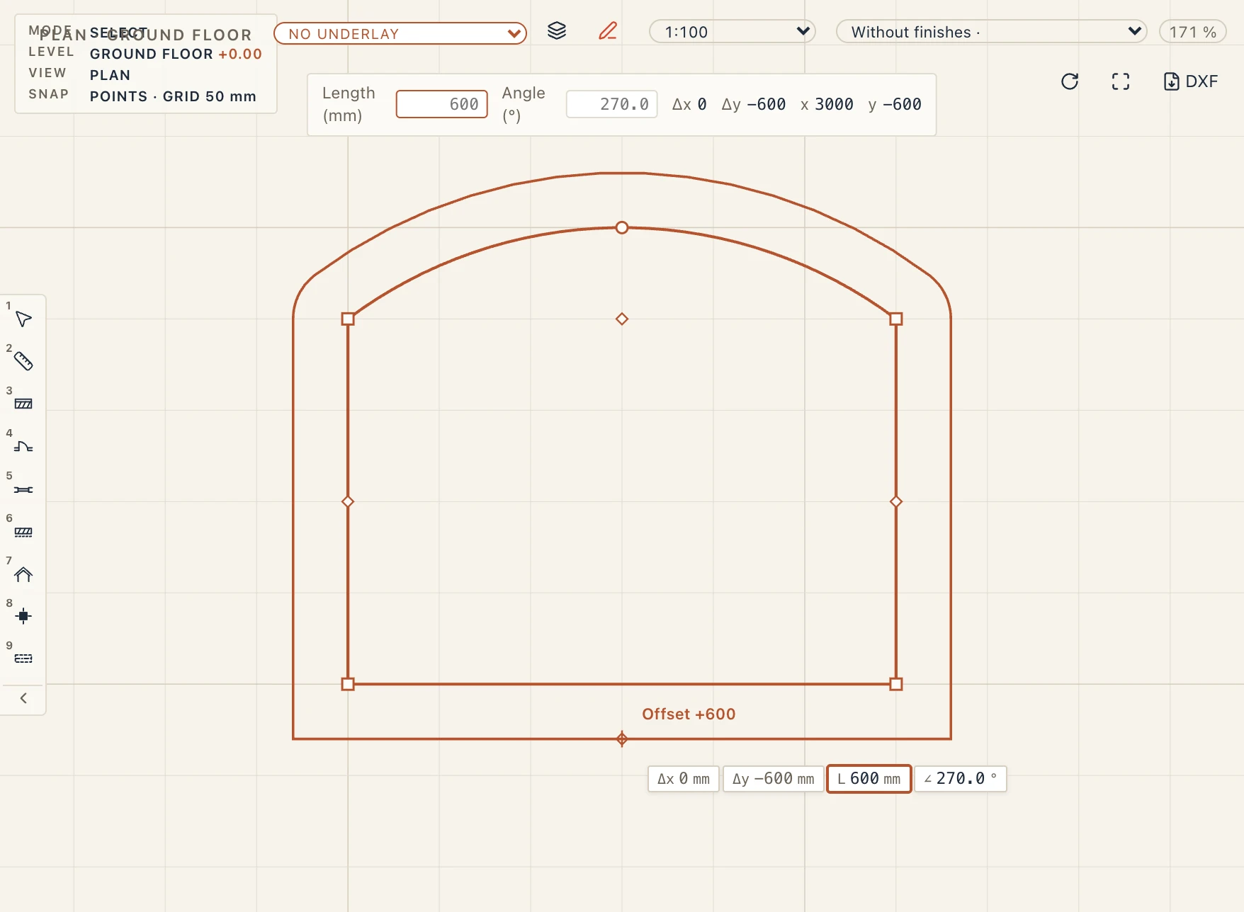
To grow or shrink the whole outline at once, every edge by the same distance (Archicad's Offset all edges), hold Shift and drag the diamond in the middle of any edge: the outline follows the cursor live, in a plan or in 3D, and the distance can be typed while dragging (Enter puts it there). Or right-click the selected floor and choose Offset outline…, then type the distance: positive goes outward, negative inward. Straight edges stay parallel and meet again at their corners; a curved edge stays an arc about its own centre, and where an arc meets another edge at a corner, growing rounds that corner. An offset that would make an edge vanish or the outline cross itself is refused, with the reason at the cursor. It works on floors, floor openings, ceilings, roofs (each edge keeps its eave or gable rule), rooms and balconies, and on several selected at once; each is one undo step.
Curved edges, fillets and round floors
The Floor tool's bar, in the command line, draws the outline as a Polygon (its corners clicked), a Rectangle (two opposite corners), a Circle (its centre, then a point on it) or Inside walls (a click inside the walls that close round it; the floor goes up to their faces). In a polygon, Lines (Space) turns into Arcs (Space): the next edges are arcs, each going on tangent from the edge before, until you press Space again. Floor opening and Ceiling have the same bar.
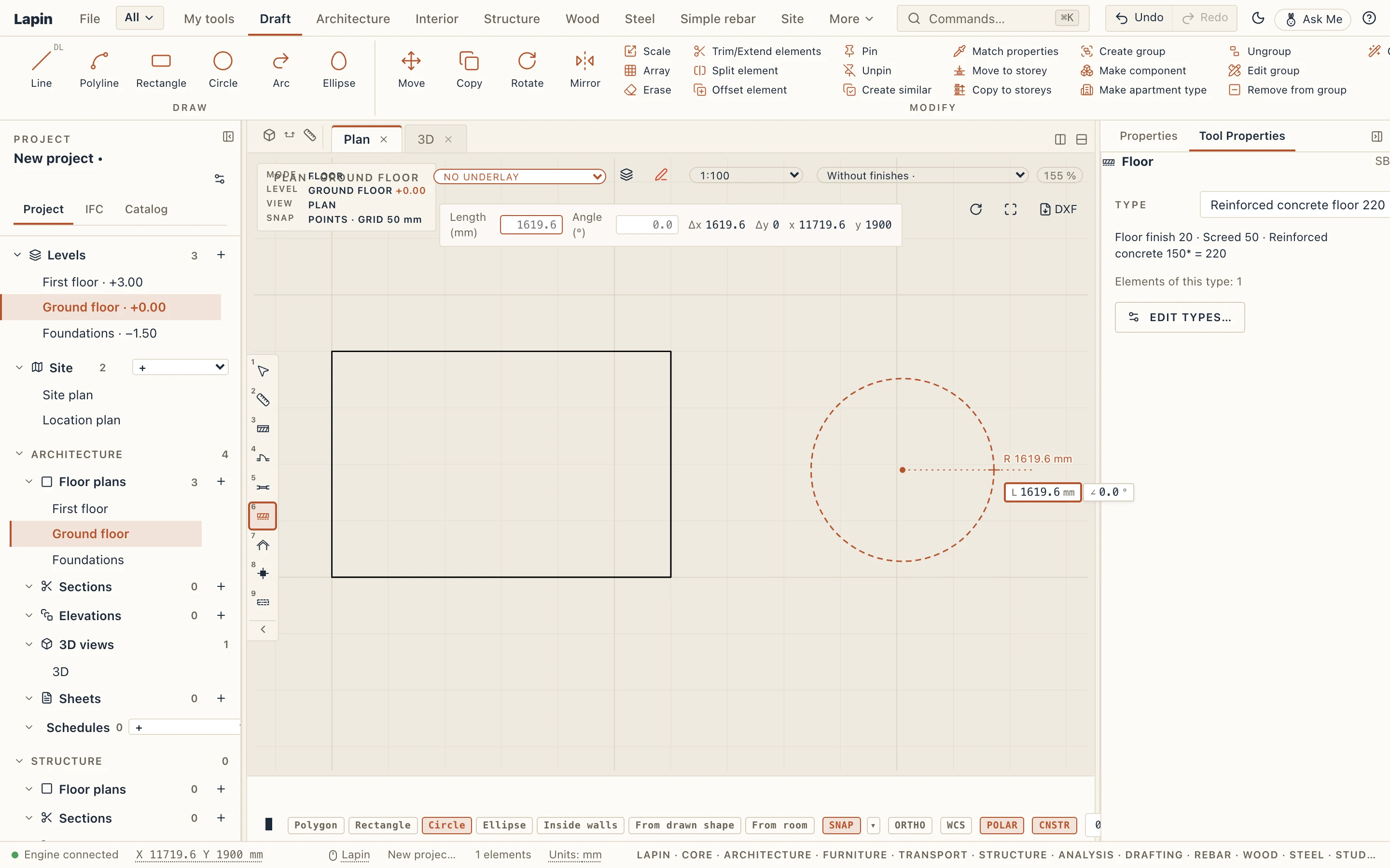
The same bar serves every outline tool (floor, floor opening, ceiling, hole, room and balcony by outline, platform, parcel), and three of its choices take the whole outline with one click: Inside walls (the walls that close round the point), From drawn shape (the smallest closed drafted shape round the point: a closed polyline, a rectangle or a circle, a circle staying round) and From room (the room round the point, with its curved edges).

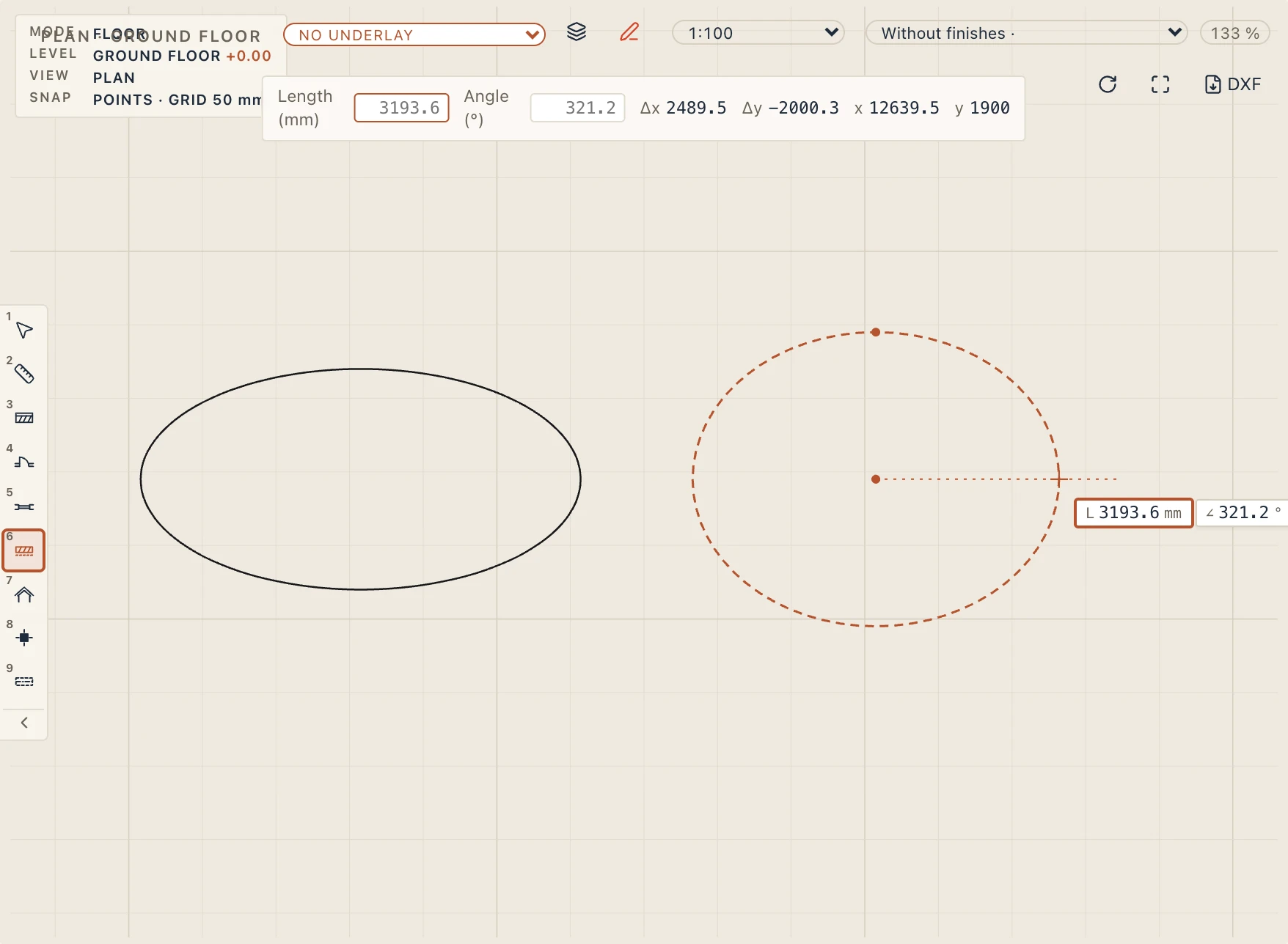
For a floor, a floor opening, a ceiling and a room by outline the bar also offers Ellipse: its centre, the end of one semi-axis, then the other. The outline's edges run along the true ellipse (four quarter edges), measured exactly; a corner moved off the ellipse turns its two edges straight, and a corner beside an elliptical edge is not filleted. IFC carries it as an IfcEllipse. From drawn shape takes a drafted ellipse the same way. A floor's or a ceiling's own hole (Hole in the outline) takes an ellipse too. Offsetting the whole outline (Shift-drag, Offset outline…) turns an elliptical edge into the true curve at that distance, laid in short straight edges (the curve at a distance from an ellipse is no ellipse); inwards it stops before the curve would fold at the ellipse's tightest bend.
An opening through a floor (a stairwell, a shaft) is Architecture → Opening set to Floor opening (SH): its outline drawn inside the floor, as a polygon whose edges may be arcs, a rectangle or a circle.
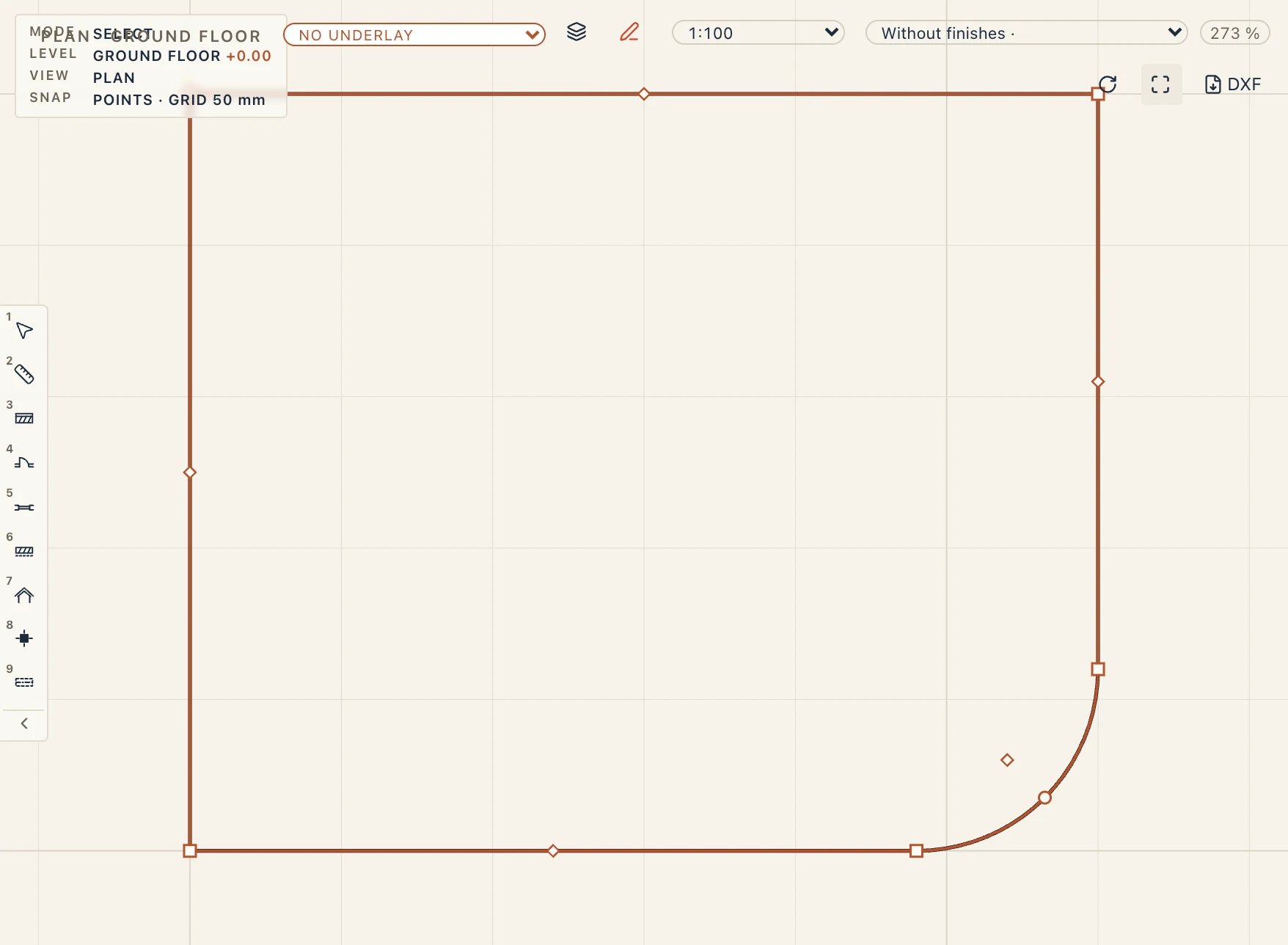
Any edge of a floor, a floor opening or a ceiling can be curved. Right-click the selected floor near an edge and choose Make arc: the edge bulges out by an eighth of its length, and a round grip appears at the middle of its arc. Drag that grip to bend the arc through the point you want (the diamond, now in the middle of the chord, still moves the edge). Make straight turns it back into a line. A corner between two straight edges can be rounded or cut: right-click it and choose Fillet corner… (type the radius) or Chamfer corner… (type how far back along each edge). The corner becomes two, where the arc or the cut meets its edges; a radius too large for the edges is refused. Each is one undo step.
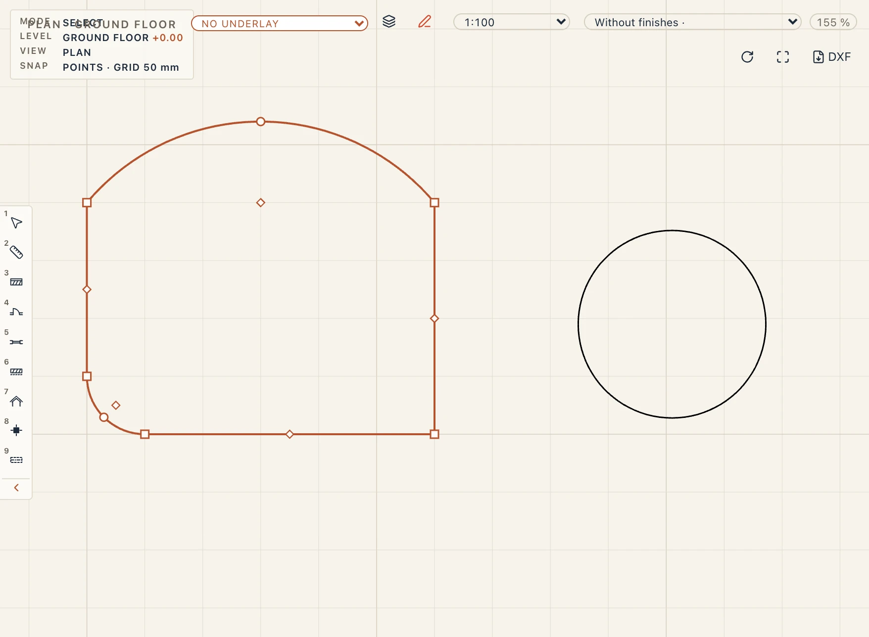
The floor is built along its arcs, no chord more than 1 mm off them, in 3D, plans and sections; its area and perimeter are measured on the true arcs. A layer that goes past a curved edge (see Layer extents) follows the arc. An opening can have curved edges too, and a curved floor can have openings. In IFC the floor carries its outline with its true arcs as its footprint (an IfcIndexedPolyCurve with arc segments), beside its body. Roofs keep straight edges, because a roof's edge rules (eave, gable) are set per straight edge.
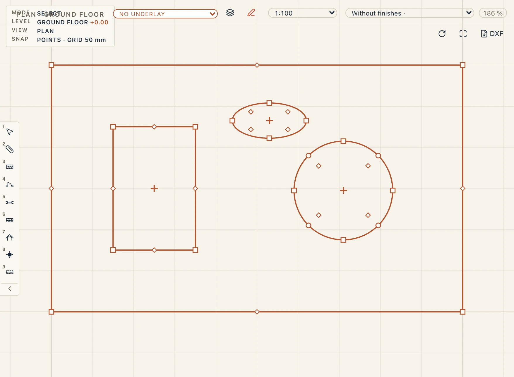
A floor or a ceiling can have holes of its own: islands cut out of its outline, part of the element, not openings of their own. Choose Hole in the outline in the Opening tool (under In a floor) and draw it inside the floor (or the floor or ceiling selected) with the same bar: a polygon whose edges may be arcs, a rectangle or a circle. Selected, the floor shows each hole's corners and edges as grips, with the same right-click (Make arc, Fillet corner…, Chamfer corner…); the cross in a hole's middle drags it, and its right-click offers Remove hole. The floor is built round its holes and its area leaves them out, measured on their true arcs; a hole must lie inside the outline, apart from the others, and an outline changed so that it no longer holds one is refused. In Edit sketch the holes are loops of the sketch too: draw another closed loop inside and Finish sketch makes it a hole (the largest loop is the outline). In IFC the holes are more curves of the floor's footprint, read back as holes. A platform (Site → Hole in platform) takes holes the same way: the ground inside a hole keeps its own levels.
Edit sketch
For more than a corner or an arc, right-click the selected floor (or floor opening, or ceiling) and choose Edit sketch (also Studio → Edit sketch). Its outline opens as a sketch on a plan of its own, one line or arc per edge, its corners held together, the floor itself hidden there; a bar over the plan says whose sketch it is and holds Draft's tools and the constraint tools (the same bar as every sketch: a part's, a sketch on a face). Draw and change it with them or the Draft tab (Line, Arc, Fillet, Trim, Extend, Offset…), and constrain and dimension it with Studio → Constraints (see Sketch constraints): change a dimension and the outline follows. Finish sketch writes it back to the floor in one undo step, the floor keeping its identity (its GlobalId); Cancel leaves the floor as it was. The sketch must be one closed outline (its edges end to end, or a circle alone); otherwise Finish says what is open.
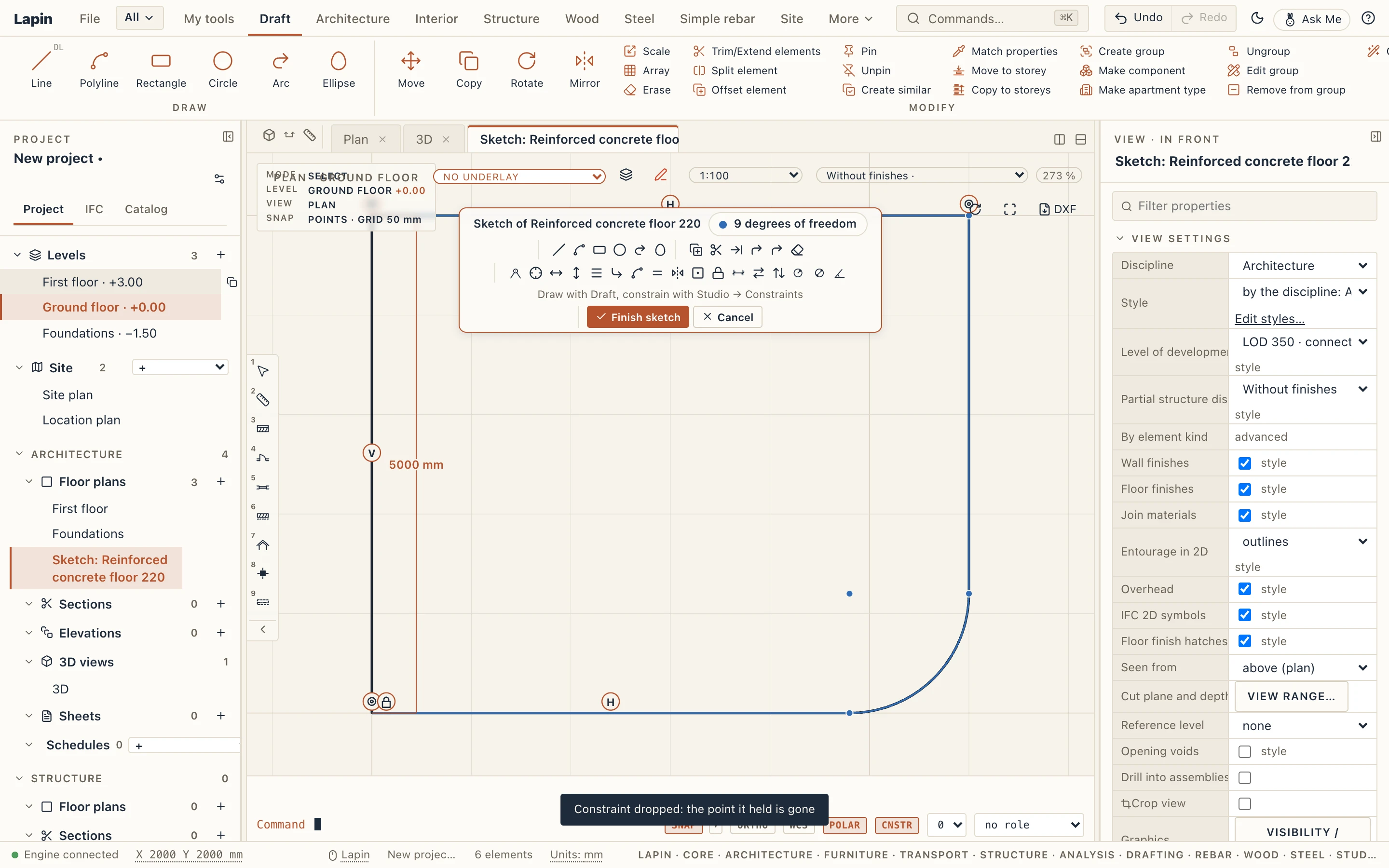
The sketch, with its constraints and dimensions, stays on the floor (it goes to IFC with the floor's design intent, in Lapin_Intent), so Edit sketch opens it again as you left it. If the outline was changed since by its grips, the sketch starts again from the outline as it is, without its constraints. A floor recognised from an IFC file gets a sketch only when you edit it; one kept as a reference is not edited this way.
A floor drawn outside the walls, in front of a door, is a porch. For the steps up to it, see Stairs.
A floor's layer can also go on past its outline, or stop short of it, all round or at one edge, typed in its properties or dragged in a plan or a section with Edit layers, and a floor type can give its floors their extents: see Layer extents. Roofs have no layer set yet (their covering, deck and framing are parts of their own), so they have no layer extents.
Beam-and-block floors
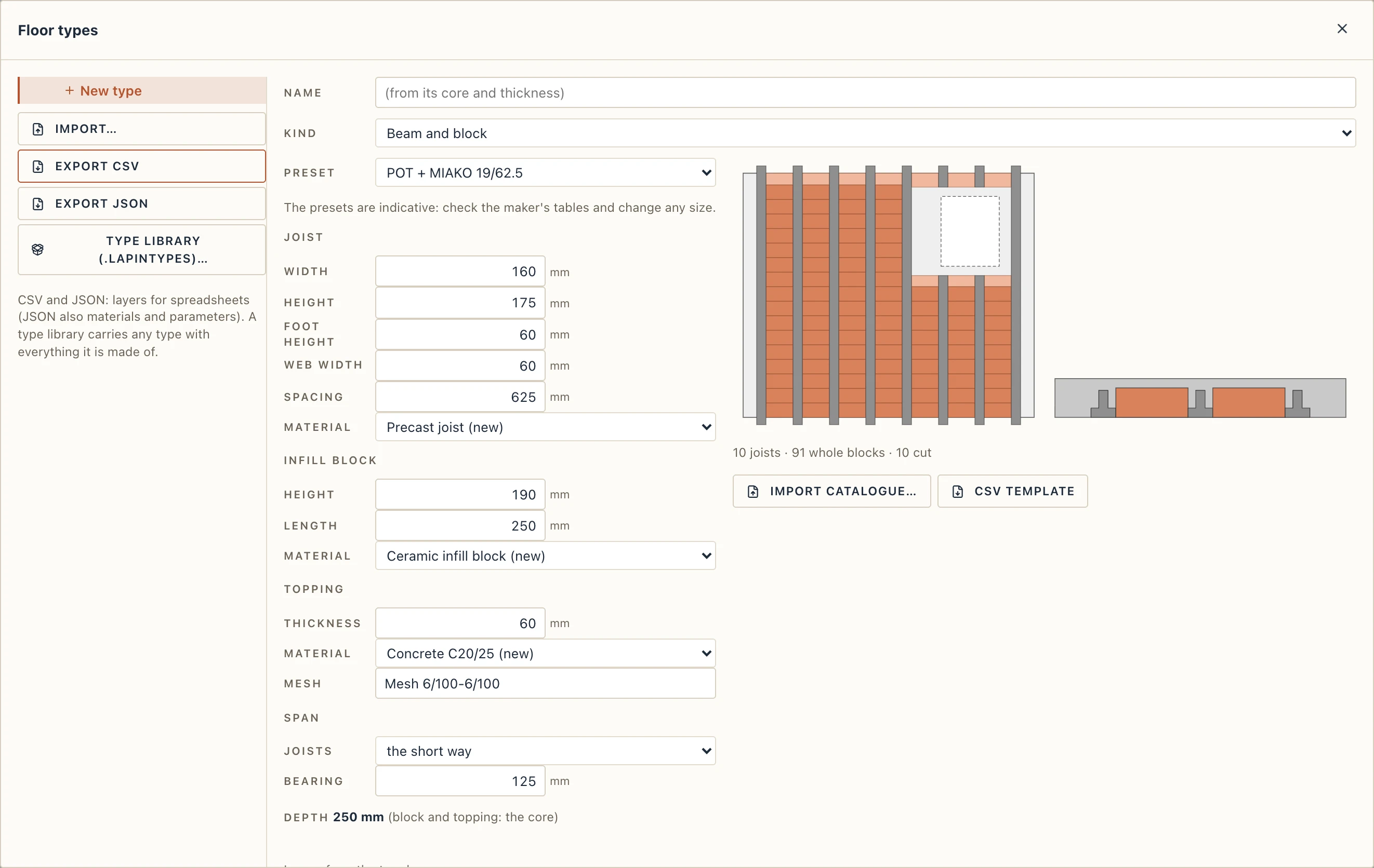
A floor type can be of beam and block instead of plain layers: precast joists (a POT joist, say) laid side by side at a spacing, ceramic infill blocks (MIAKO) between them, and a cast concrete topping over them. In Floor types, set Kind to Beam and block and fill in:
- Preset. A few systems to start from (POT + MIAKO 19/62.5, 19/50, 23/62.5, 25/50). They are indicative: check the maker's tables and change any size; once a size is changed the preset reads Own sizes.
- Joist: the foot's Width and Foot height, the Web width, the joist's Height, its Spacing axis to axis and its Material.
- Infill block: its Height, its Length along the joists and its Material. Its width is the gap between the joists' feet.
- Topping: its Thickness, its Material, and the Mesh in it (a name, measured by the floor's area; empty, none).
- Span: the joists run the short way of the floor, along x, along y or at an angle; the Bearing is how far they go into the supports past the floor's edge (125 mm by default), so draw the floor to the supports' faces.
The Depth is worked out: the block and the topping. It is the type's core, set by itself when the type is saved; the layers over it (a screed, a finish) stay as they are. Beside the fields the engine lays out a sample floor with an opening, in plan and in section, as it will build yours, and counts its joists and blocks.
A floor of the type is built of its joists (each from edge to edge and into the supports), whole blocks from the start of each row and one cut at its end, and the cast concrete: the topping, the ribs over the joists' feet, the strips at the sides and, round an opening, the headers that take the joists stopped short of it. Its properties set its own Span direction: the type's, or across one of its edges (the edge the joists bear on). A plan draws the span arrow and, in a detail plan, each joist's axis; a section cuts the joists, the blocks and the concrete, each hatched by its material.
Beam and block floors in the schedules lists, per floor, the joists by their ordered length (rounded up to 250 mm), the whole and the cut blocks, the cast concrete and the mesh's area; the floor's quantities carry the same. IFC writes the floor as an IfcSlab whose parts are the joists (IfcBeam JOIST), the blocks and the concrete (IfcBuildingElementPart), each of its material; a part keeps its GlobalId when the floor is rebuilt.
Your own catalogue comes in from a spreadsheet: Import catalogue… reads a CSV (one row a system, sizes in millimetres; CSV template gives the columns) and makes a floor type of each row, or changes the type of the same name, in one step to undo.
Modify → Split element on a floor or a ceiling asks for two points of a split line: it runs on past them and must cross the outline exactly twice. The floor becomes two floors; the part you clicked keeps the id (its GlobalId in IFC), arcs on the edges stay arcs (a cut arc stays an arc), and a floor opening goes with the part it lies in. An opening the line crosses refuses. Modify → Trim/Extend elements takes a straight boundary (a wall, a beam or a drafted line) and cuts the floor or ceiling there, keeping the side you click.
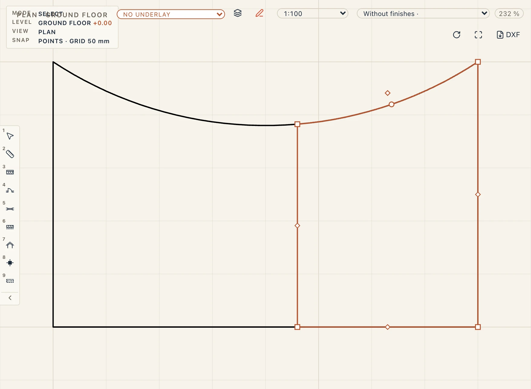
A floor's own holes go to the part they lie in; a layer that reaches past a curved edge keeps doing so on both parts; a false ceiling's grid stays where it was, each light or diffuser in the part its cell lies in. A floor with an elliptical edge is not cut by a line.
A roof is split and trimmed the same way. Each part keeps the rules of its edges (eave or gable, pitch, overhang), and the cut is a gable with no overhang; the cut is allowed only where it leaves the roof as it was, each part's slopes standing where the roof's stood, as across a gable roof's ridge or along it. Elsewhere it is refused (would change its slopes): a part's slopes would rise to new ridges. Roof windows, dormers and downpipes go to their part. A barrel roof is not cut.
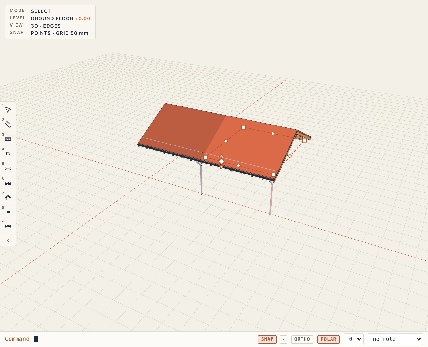
Roofs
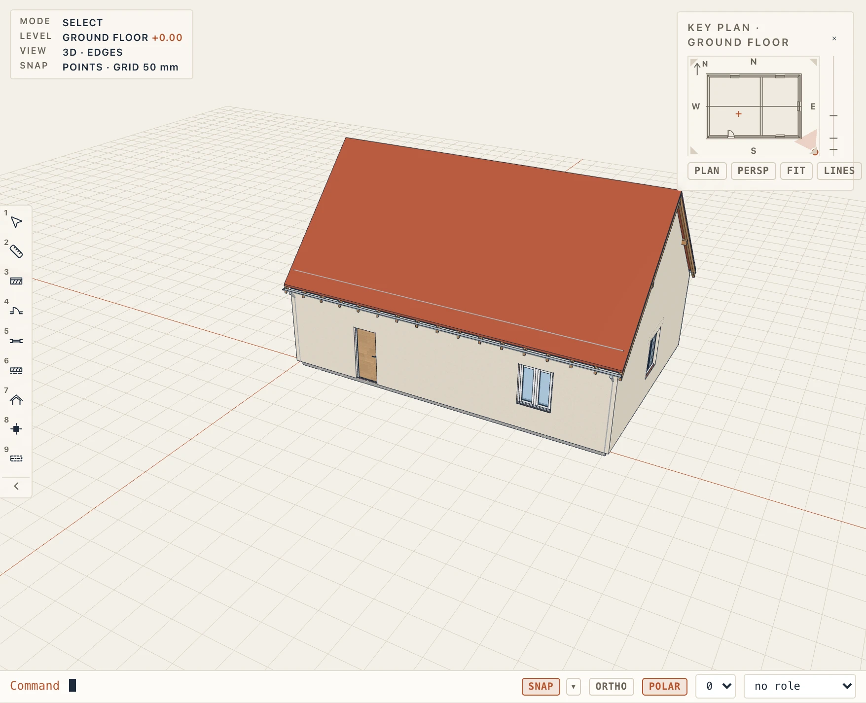
Choose Architecture → Roof (RF) and click the outline of the walls under it. Lapin builds the roof over that outline, at the top of its level.
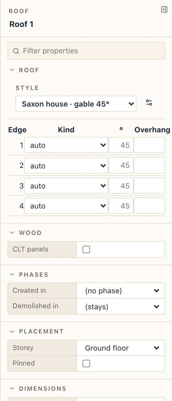
Select the roof to change it in the properties panel:
- Shape. Hip, gable, shed, mansard, barrel or flat. A barrel roof is a curved vault between two gable ends; Barrel: rise sets how high it rises at the crown, at most half its span.
- Pitch and overhang for the whole roof.
- Ridge direction (gable, shed): auto, x or y. A shed roof's ridge is its high side: on x it falls towards −y, on y towards −x; Shed: flip the slope makes it fall the other way.
- Each edge with its own kind (eave or gable), pitch and overhang. A mansard with gable edges is a gambrel.
- Style. The roof styles give a whole look in one choice: the covering, the eaves, the gutters and downpipes.
- Covering material. The covering is made of a project material, the covering's own by default (Clay tile, Metal sheet, Slate…), made in the covering's colour the first time a roof needs it. Pick another one in the properties or in the configurator's Covering and drainage; changing the covering changes it too, unless you chose one. Elevations and sections hatch the covering by that material (tiles, shingles and slates in level courses, metal sheet in vertical seams, unless you give it an Elevation hatch of its own), a section draws the cut covering with the material's section hatch, and IFC, the quantity takeoff and the estimate list the covering under its material.
- Covering thickness. Empty, the covering is as thick as the catalogue's (a membrane 2 cm, metal sheet 3 cm, tiles 5 cm…); type one to give it its own. A roof imported from another program keeps its file's.
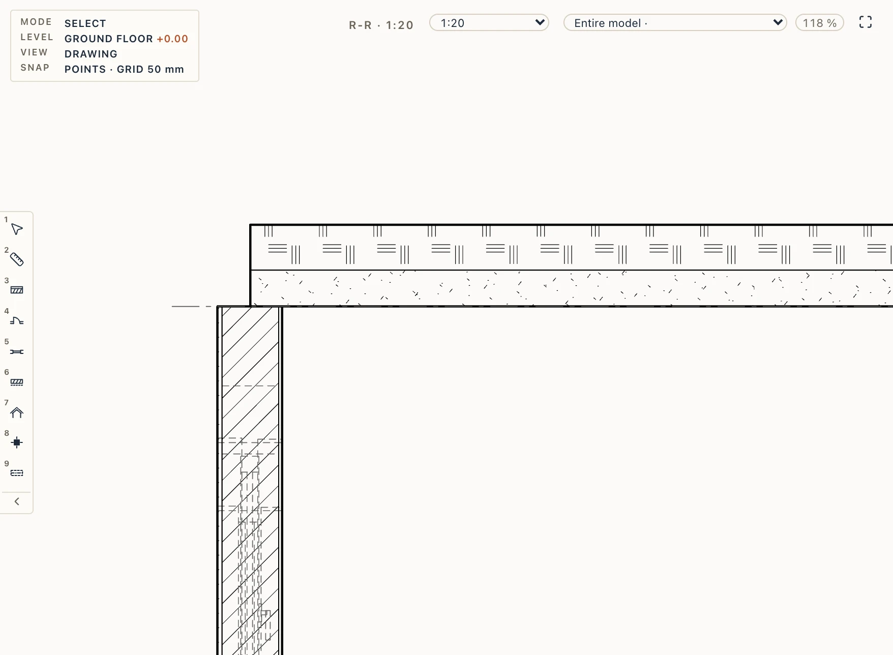
- Deck. A flat roof, a barrel vault and a roof with Structure none have a deck under the covering, a part of its own: Deck material (Reinforced concrete by default, made the first time a roof needs it) and Deck thickness (16 cm by default), in the properties or in the configurator's Framing. The covering lies on it, so the roof stays as thick as the two together. A section draws two bands, each hatched by its material; roof windows go through both; a wall attached to a flat roof rises to the deck's underside; IFC writes the deck and the covering as two roof slabs of their materials, and the quantity takeoff and the estimate measure the deck (area and volume) and the covering (area) each under its material. The properties show these two fields only on a roof without framing, and the rafters' fields (sections, spacing, grade, purlins, tails) only on a framed one; a field that applies to one shape only (the mansard's, the vault's rise, the shed's flip) shows on that shape.
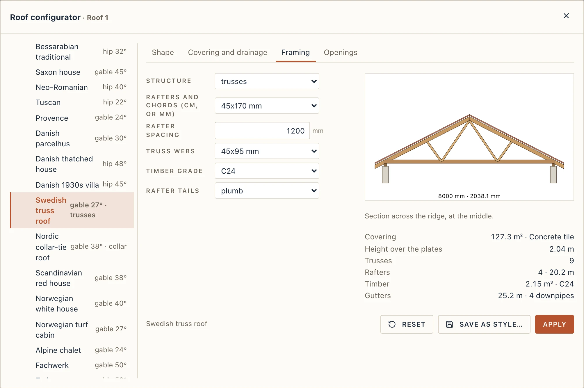
Roof configurator (the button beside the style, or Architecture → Roof configurator with a roof selected) gathers everything in one place: the styles on the left, then the shape and its edges, the covering and drainage, the framing and the openings, over a plan of the roof (click an edge to make it auto, an eave or a gable) and, for the framing, a section across the ridge with the truss or couple at the middle. Pick a style to start from and change any field by hand; Apply makes it one undo step. Save as style… keeps the roof as it is configured as a style of the project, listed under Project above the catalogue's (and in the properties panel's list) for other roofs and new ones; Update style saves the changes into it again, and every roof of the style follows. A project style can be renamed or deleted; its roofs keep how they look.
Gutters and downpipes. In the configurator's Covering and drainage the gutter takes its size, how far out of the eave and how far below the covering it hangs, its fall to the outlets (mm/m) and its end caps; the edges' table switches each eave's gutter on or off. The downpipes start as the roof's own, one every 10 m; Make them editable turns them into elements, and Architecture → Downpipe adds one with a click on a gutter. A downpipe's grip slides it along its gutter only; its properties set its diameter, the shoe at its foot and its route, a chain of segments each with its length and its angle from the vertical (towards the wall), the last one down to the ground. In IFC a gutter is an IfcPipeSegment GUTTER and a downpipe a rigid segment named Downpipe.
The walls on the roof's level stop under it and rise to its gables by themselves, under a curved roof too. A wall on another level follows the roof after Architecture → Attach to roof (AR): select the walls, then click the roof. The same tool takes any other body over the walls: a Studio solid, a slab, a beam, an element imported from IFC. The walls rise to its underside and are cut along it, whatever its shape. Detach from roof undoes it.
Architecture → Opening set to Roof window or Dormer adds an opening to a roof: click on a slope. They belong to the roof. Select the roof, and each one shows its grips in plan. Drag the grip at its middle to move it on the roof. Drag a roof window's edge or corner grips to resize it on its slope (the opposite edge stays where it is; you can type the length as you drag). The width runs along the eave and the length up the slope, measured on the slope. A dormer has a grip at each side for its width. A change that would not fit on the roof is refused. To remove one, right-click its grip and choose Remove roof window (or Remove dormer), press Delete while the cursor is over its grip, or Ctrl/⌘-click its middle grip. The roof's properties list them too: type a window's width and length there, or click × to remove it. A dormer's roof is covered in the roof's covering material and measured with it: the roof's quantities list the dormer covering apart (the area of its slopes, the number of dormers), so the quantity takeoff by material, the estimate and a planning task on the covering count the roof's slopes (less the dormers' notches) and the dormers' roofs, each once.
Timber framing
Structure sets how the roof is framed:
- rafters: rafters on purlins, with a ridge beam.
- collar: couples of rafters with a level collar tie at Collar ties: share of the rise (two thirds by default), no purlins.
- trusses: prefabricated trusses along the main ridge, at the Rafter spacing: top chords on the slopes, a bottom chord on the wall plates, W webs (a mono truss on a shed roof). A hip roof's ends keep their rafters.
- none: a deck, no timber.
Rafters and chords takes the old sections in cm or the Nordic ones in mm (45×95 to 45×245); Truss webs and Timber grade (C14 to C30, glulam) go with them. The rafters sit on the wall plate by a bird's mouth (Rafter seat on the wall plate) and end at the eave plumb or square (Rafter tails). The Swedish truss roof and Nordic collar-tie roof styles bring their framing with them.
Every member is a part of its own: the Roof timber schedule lists them as a cutting list (member, section, grade, length, pieces, volume), and IFC gets each as an IfcMember of its type, each truss as an IfcElementAssembly.
False ceilings
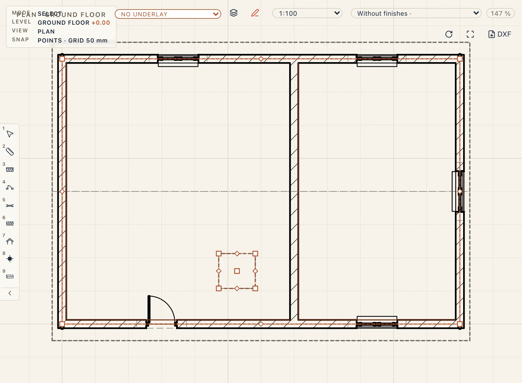
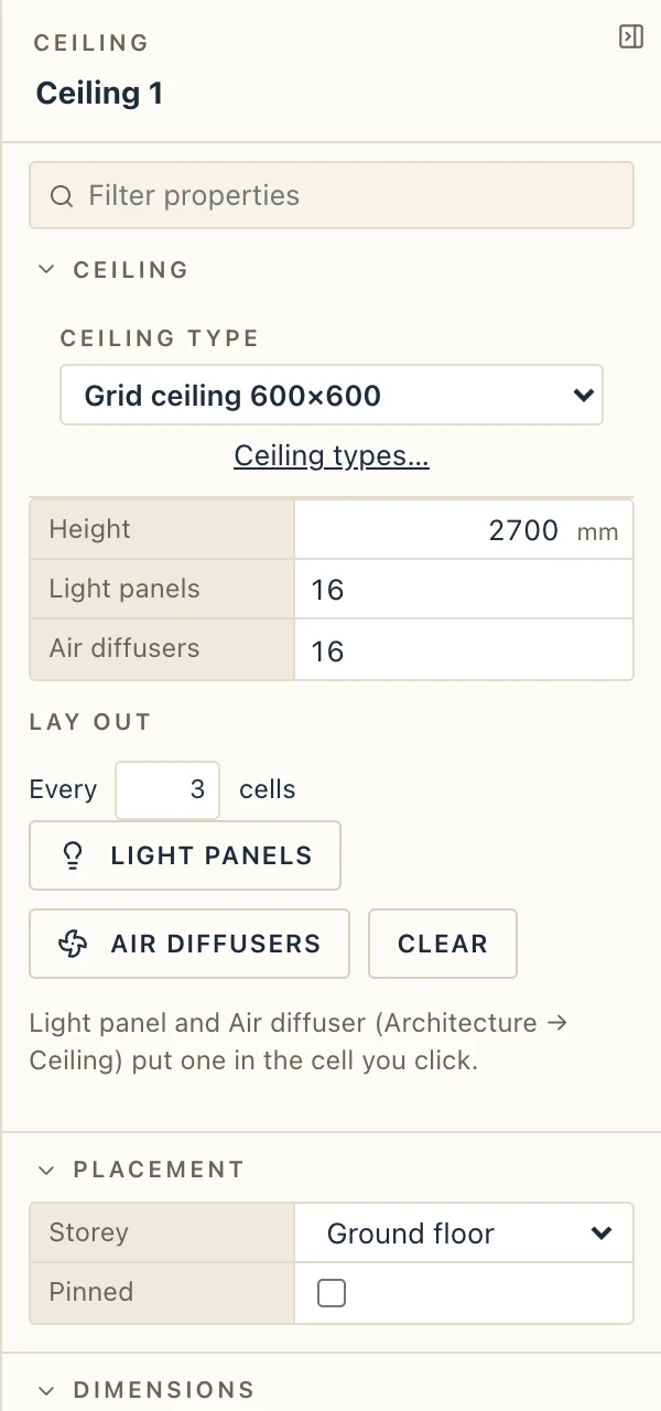
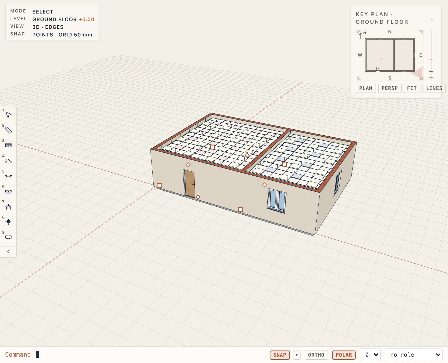
Interior → Ceiling (CG) draws a false ceiling over an outline you click; Ceiling in a room fills the room you click, following its outline. A ceiling hangs at its Height over the storey (2700 mm unless you change it in its properties).
Its type, in Interior → Ceiling types, sets the System: Tiles on an exposed grid (the tile's width, length and thickness, the grid's face width, depth and rotation, hangers up to the structure at their spacing) or Plasterboard, continuous. The grid is centred on the ceiling, so the cut tiles at the edges come out even.
Light panel and Air diffuser put one in the cell you click; click the cell again with the other tool to change it. In the properties panel, Lay out puts light panels or air diffusers every so many cells, and Clear takes them away. The schedules count the whole tiles, the light panels and the diffusers, and the ceiling goes to IFC as an IfcCovering of type CEILING.
Skirtings
Interior → Skirting in room (SK) lays a skirting board round the room you click, along the walls' faces, broken at each door (any opening that comes down to the floor); clicked inside walls with no room, it follows them the same way. A room's skirting follows the room: move a wall or a door and the skirting goes with it. Skirting draws one along a line you click on a wall's face (Enter finishes); the board goes on the side away from the wall, and Flip side in its properties turns it over.
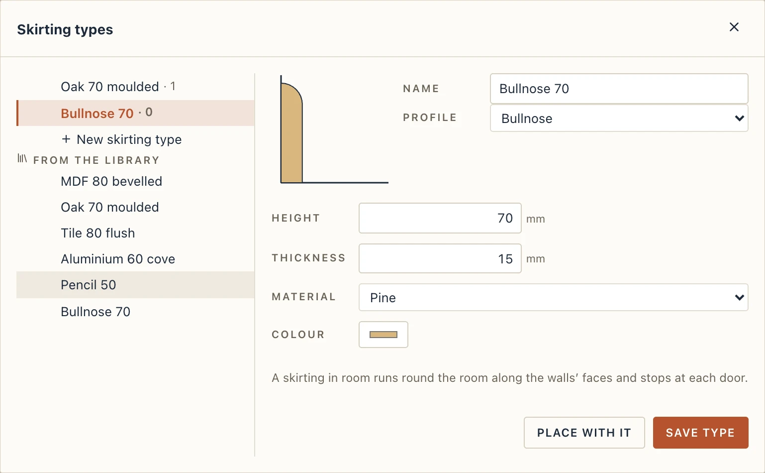
Its type, in Interior → Skirting types, sets the Profile — Flush (square), Bevelled (MDF), Moulded (wooden), Cove foot (metal), Pencil round or Bullnose, drawn beside it to scale — the Height (40 to 300 mm), the Thickness (5 to 40 mm), the Material and its colour. From the library brings ready-made types into the project: MDF 80 bevelled, Oak 70 moulded, Tile 80 flush, Aluminium 60 cove, Pencil 50 and Bullnose 70. While a skirting tool is on, the properties panel shows the type it lays, to choose before the click.
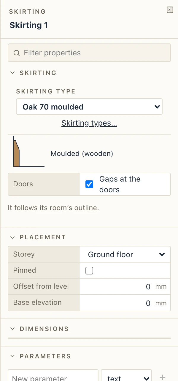
A skirting's properties hold its type, its Base offset over the floor (under Dimensions) and Gaps at the doors (off, it runs on across them). Skirting schedule (or Skirtings in the project browser's list of new schedules) lists them by type with their pieces and length, the doors' gaps left out. The board is mitred at the corners; a plan draws its front edge, and a skirting goes to IFC as an IfcCovering of type SKIRTINGBOARD, of an IfcCoveringType of the same.