Podręcznik użytkownika
Shop drawings
Make an element's own sheet in one dialog: its views drawn from its own axes, with its overall dimensions and its data, always live.
What a shop drawing is
A shop drawing is the drawing of one element: a steel member, a Studio part, a plate. It has its own sheet with the title block, the views you ticked, drawn from the element's own axes (X along the part, Y across it, Z up) and not from the project's, the element's overall dimensions, and a table of its data (name, material, profile, weight and the like) above the title block.
The drawing is always live. The views are views of the model like any other, so when you change the element the sheet changes with it; nothing is a copy.
Make a drawing
Select one element, then right-click it and choose Make drawing…, or click Shop drawing in the Annotate tab. If nothing is selected, or more than one element, Lapin asks you to select a single one.
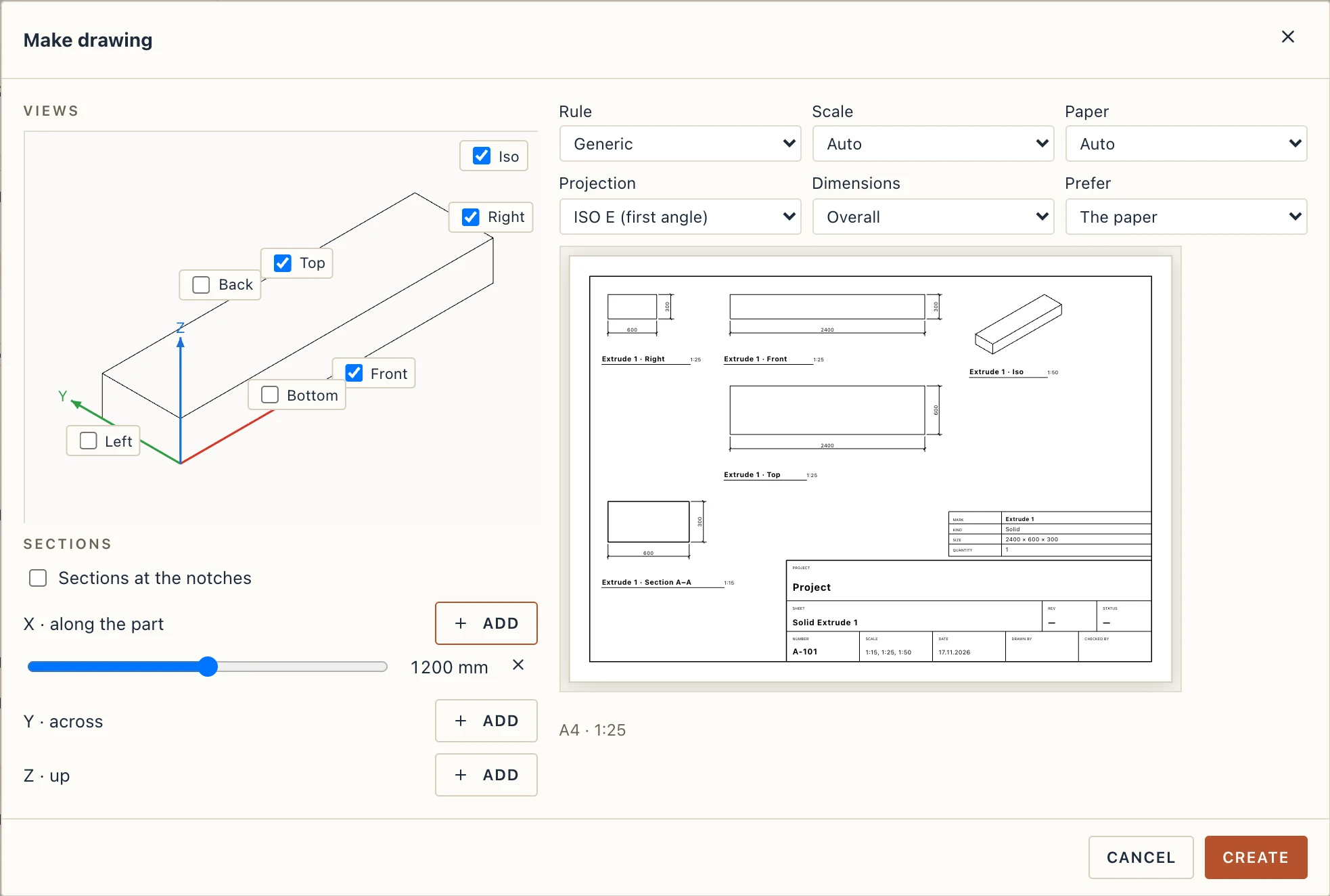
On the left is the element itself, drawn by the engine in iso with its axes: X red, Y green, Z blue. Each of its six faces has a check box: Front, Back, Top, Bottom, Left and Right. Tick a face to put the view of that face on the sheet. The Iso box adds the iso view.
Under it, Sections are cuts parallel to the faces. Each axis has an Add button, and every section you add has a slider along that axis, from one end of the part to the other, with its position in millimetres from the part's origin. Add as many as you need; the cross at the end of a row removes one.
On the right you choose how the sheet is made:
- Rule: the set of views, dimensions and sections the element's kind starts from. The rule of its kind comes first; another rule fills the boxes again.
- Scale: Auto, or 1:1 to 1:100.
- Paper: Auto, or A4 to A0. With Auto Lapin takes the smallest paper the views fit on.
- Projection: ISO E (first angle) is the European way: the top view is drawn under the front view, the left view to its right. Third angle puts each view on the side it is seen from. The project's projection is the starting choice.
- Dimensions: Overall gives the length, width and height of the part on the views; None leaves them out.
- Prefer: when both cannot be kept, whether the paper or the scale you chose wins.
The preview under the choices is the real sheet, composed by the engine each time you change something. Under it you read the paper and the scale it took. If the views do not fit, a warning says so: choose a larger paper or a smaller scale.
The choices start from the rule, so most of the time you can click Create at once.
The sheet
Create makes the drawing as one step, and opens its sheet.
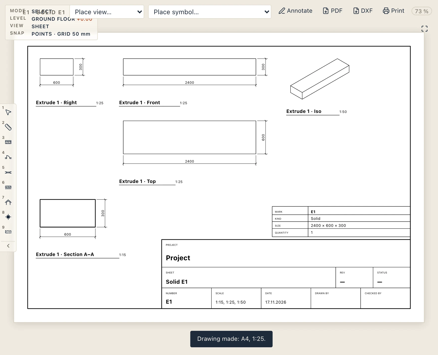
The views are ordinary views on an ordinary sheet: move them, change their scale, edit the title block. The views show only their element: the rest of the model is not drawn behind it.
Steel members: holes, copes and cut ends
A steel member (a member, or a steel beam or column) is drawn by the Steel member rule: its front and top views, an iso, and its features dimensioned. A steel plate is drawn by the Steel plate rule: its face and its edge.
- Holes seen face on are dimensioned in runs: a chain from the member's end through the first and last hole of each run to its other end, a run of equal pitch written 4×80 = 320; over it the ordinates of every hole from the member's start; on the left where the rows of holes are across the member; by each run its count and diameter (5× Ø22).
- A cope (an end notched back) gets its length and its depth, and Sections at the notches adds a section through the middle of each one.
- An end cut off square shows its angle in the view that sees it: about the side from the front, about the up from above.
Choose Dimensions → Features (holes, notches) for any element; the plain Overall gives the length and the height only. A plate's holes and a Studio part's are found from its body.
Holes are drilled in a run with the command steel.addHoles (station, count, pitch, diameter, through the web or a flange), from Python or the assistant; an SDNF file's holes come in with their members.
The dimensions are worked out every time the view is drawn, so they follow the member: drill a hole elsewhere, lengthen it, and the sheet says so. A string you move stays where you put it as the member changes (drawing.moveDimension).
Marks: identical parts
Identical parts share a mark (P12, C3, PL4…) and a drawing says how many there are. Two parts are identical when they have the same shape in their own axes, to half a millimetre, the same material and the same finish, whichever way they lie in the building: a copy turned or moved, or a member drawn from its other end, is the same part. A mirror image is not: it gets a mark of its own.
Annotate → Number parts numbers the project's steel parts and every part that has a shop drawing; Make drawing… numbers its part by itself. The sheet's number is the mark, its name the part's kind and mark, and the data table shows the mark and the quantity. Tags, schedules and filters read them as the fields {mark} and {qty}.
Marks do not move once given, like the parts' ids:
- a new kind of part takes the next number of its prefix (the biggest parts first);
- a part you edit keeps its mark when it was the only one of it; when the mark has other parts, the edited one takes a new mark and the others keep theirs;
- once a part's sheet has gone out in an issue, its mark is frozen: an edited part takes a new mark;
- a mark whose parts were all deleted stays free until you renumber (the command
marks.renumber, which only the host of a shared session can run).
A steel project numbered for the first time keeps the marks its steel members schedule showed (C1, R1, P1…), except where one mark there held mirror images: the second takes a new number.
Which side of a part is its front is worked out from the part; to turn it for all the parts of its mark use marks.setFrame (a quarter turn about its height, or upside down). It is kept with the mark, never on the part, so a part from an IFC file is never written to.
Making it again
Open Make drawing… on the same element and the button reads Update. Updating keeps the sheet and its views, and your own edits on them (a view renamed, a line or a note drawn on a view, elements hidden in it); the views are laid out on the sheet again. One Undo removes the whole drawing: the sheet, its views and the drawing itself.